

Combined type carbon fiber bottom cradle of spinning machine
A combined and component-based technology, applied to spinning machines, textiles, papermaking, drafting equipment, etc., can solve problems such as poor spinning quality and large differences between spindles
- Summary
- Abstract
- Description
- Claims
- Application Information
AI Technical Summary
Problems solved by technology
Method used
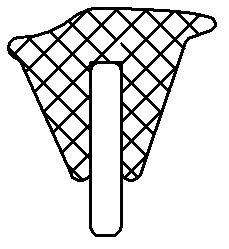
Image

Examples
Embodiment 1
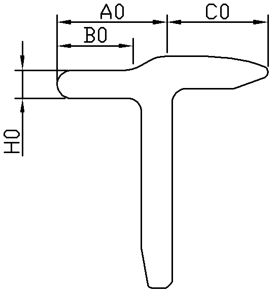
[0019] Experimental model: FA506, Changde 142 spring cradle pressurized; spinning 40 counts of combed cotton yarn; using combined rubber ring lower pins. The length of the straight part B1 in Part B is 5 mm, and the length of the curved part connected to the straight part B1 is correspondingly 19 mm, and the distance A1 from the highest point to the front edge of the straight part is 10.23 mm, and the distance from the highest point to the apron The distance C1 of the tail end of the lower pin is correspondingly 13.77 millimeters, and the degree difference H1 between the curved part and the straight part is 3.3 millimeters; the total height H2 of the second part is 20 millimeters, and the total width L2 is 35 millimeters; The component fits into the mounting groove, which has a depth dimension H3 of 13.6 mm and a width L3 of 3.5 mm. The material is carbon fiber. The experimental results are shown in Table 1:
[0020] Table 1
[0021]
Embodiment 2
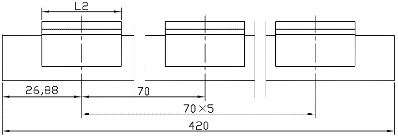
[0023]Experimental model: FA1520, pressurized by Yuhua pneumatic cradle; spinning combed cotton / polyester 55 / 4545 count yarn; using combined rubber ring. The structural size of the lower pin is: the structural size of the first part is 420×3.5×20mm . The length of the straight part B1 in part B is 5 mm, and the length of the curved part connected to the straight part B1 is correspondingly 19 mm, and the distance A1 from the highest point to the front edge of the straight part is 10.73 mm, and the distance from the highest point to the apron The distance C1 of the tail end of the lower pin is correspondingly 13.27 millimeters, and the degree difference H1 between the curved part and the straight part is 3.2 millimeters; the total height H2 of the second part is 20 millimeters, and the total width L2 is 35 millimeters; The component fits into the mounting groove, which has a depth dimension H3 of 13.6 mm and a width L3 of 3.5 mm. The material is carbon fiber. The experimental ...
Embodiment 3
[0027] Experimental model: BS516, Changde 142 spring cradle pressurized; spinning combed cotton / polyester 60 / 4032 count yarn; using combined rubber ring. The structural size of the lower pin is: the structural size of the first part is 420×3.5×20mm . The length of the straight part B1 in Part B is 5 mm, and the length of the curved part connected to the straight part B1 is correspondingly 19 mm, and the distance A1 from the highest point to the front edge of the straight part is 10.23 mm, and the distance from the highest point to the apron The distance C1 of the tail end of the lower pin is correspondingly 13.77 millimeters, and the degree difference H1 between the curved part and the straight part is 3.3 millimeters; the total height H2 of the second part is 20 millimeters, and the total width L2 is 35 millimeters; The component fits into the mounting groove, which has a depth dimension H3 of 13.6 mm and a width L3 of 3.5 mm. The material is carbon fiber. The experimental ...
PUM
| Property | Measurement | Unit |
|---|---|---|
| length | aaaaa | aaaaa |
| length | aaaaa | aaaaa |
Abstract
Description
Claims
Application Information