Laser emission optical system easily coupled with laser-optical fiber combination and provided with adjustable beam divergence angle

An optical system and laser emission technology, applied in the field of optical systems, can solve the problems of inability to convert to adapt to the divergence angle of optical fiber and beam, high cost, low efficiency, etc., and achieve low development and deployment costs, wide application range, and high system reliability Effect

Active Publication Date: 2011-11-23
南京英田激光科技有限公司
View PDF6 Cites 5 Cited by
  • Summary
  • Abstract
  • Description
  • Claims
  • Application Information

AI Technical Summary

Problems solved by technology

[0006] The laser emitting optical system must not only satisfy different core diameters, different fiber numerical apertures, high power, and high brightness fiber-coupled laser output, but also set different beam divergence angles according to different requirements of different systems. Traditional laser emitting optical systems are difficult satisfy both conditions
Even if the traditional laser emitting optical system meets the requirements at the same time, it is a dedicated system for specific wavelength lasers, specific fiber core diameters, and specific beam divergence angles, and cannot be converted to adapt to different optical fibers and beam divergence angles. Has been caught in the cycle of high cost and low efficiency

Method used


Image

  • Laser emission optical system easily coupled with laser-optical fiber combination and provided with adjustable beam divergence angle
  • Laser emission optical system easily coupled with laser-optical fiber combination and provided with adjustable beam divergence angle
  • Laser emission optical system easily coupled with laser-optical fiber combination and provided with adjustable beam divergence angle

Examples


Embodiment 1

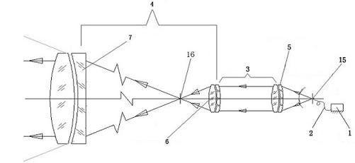
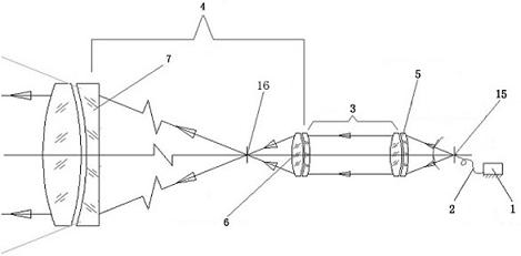
[0047] Embodiment 1: A laser emitting optical system that is easy to couple with a laser-fiber group and has an adjustable beam spread angle. The system includes a light source 1 , a beam transmission fiber 2 , an image transfer system 3 and a transmitting telescope system 4 . One end of the image transfer system 3 includes a beam expander collimator mirror 5 connected to the beam optical fiber 2, and the beam expander collimator mirror at the other end of the image transfer system 3 is the eyepiece 6 of the transmitting telescope system 4, and the image transfer system 3 It is connected with the transmitting telescope system 4 through the eyepiece 6, and the transmitting telescope system 4 also includes an objective lens 7, and the beam-transmitting optical fiber 2 drawn from the light source 1 is coupled with the image transfer system 3; 2 enters the image relay system 3, after the beam is expanded, collimated and magnified by the image relay system 3, the light leaves the t...

Embodiment 2

[0062] Embodiment 2: Replace the light source with an L-band tunable DFB laser. The power is 11 dBm; the channel spacing is 25 / 50 GHz; the spectral linewidth is 3-10 MHz; the frequency error is -1.5-1.5 GHz; the side mode suppression ratio is 43-52 dB; the photoelectric isolation is 45 dB; at 20MHz-10GHz The relative intensity noise of the test is -152 ~ -145 dB / Hz; the polarization extinction ratio is 20 dB.

[0063] Fiber can adopt the following specifications:

[0064] The peak absorption is 17.5dB / m at 1530nm, the numerical aperture NA is 0.25, the mode field diameter is 5.2um, the cutoff wavelength is 1250nm, the cladding diameter is 125um, and the coating layer diameter is 250um.

[0065] The peak absorption is 17.5dB / m at 1530nm, the numerical aperture NA is 0.25, the mode field diameter is 5.2um, the cutoff wavelength is 1250nm, the cladding diameter is 80um, and the coating layer diameter is 165um.

[0066] The peak absorption is 20dB / m at 1530nm, the numerical aper...

Embodiment 3

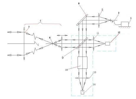
[0072] Embodiment 3: The laser emitting optical system includes a light source 1, a beam transmission fiber 2, an image transfer system 3, a transmitting telescope system 4, a tilting mirror 8, a beam splitter 9, an attenuation plate assembly 10, a receiving optical system 11, and a receiver 12 , precisely pointing to the monitoring optical system 13 and the detector 14 . One end of the image transfer system 3 includes a beam expander collimator mirror 5 connected to the beam optical fiber 2, and the beam expander collimator mirror at the other end of the image transfer system 3 is the eyepiece 6 of the transmitting telescope system 4, and the image transfer system 3 It is connected with the transmitting telescope system 4 through the eyepiece 6 , and the transmitting telescope system 4 also includes an objective lens 7 , and the optical fiber 2 leading out from the light source 1 is coupled with the transfer system 3 . The tilting mirror 8 is located in the image transfer sys...


PUM


Abstract

The invention discloses a laser emission optical system easily coupled with a laser-optical fiber combination and provided with an adjustable beam divergence angle. The optical system comprises a light source, a light beam transmission optical fiber, an image transferring system and a transmitter-telescope system. One end of the image transferring system comprises a beam-expanding collimator lens connected with the light beam transmission optical fiber, a beam-expanding collimator lens at the other end of the image transferring system is an ocular lens of the transmitter-telescope system, and the image transferring system is connected with the transmitter-telescope system through the ocular lens; the transmitter-telescope system further comprises an objective lens, and the light beam transmission optical fiber led out from the light source is coupled with the image transferring system. The system can be easily coupled with the laser-optical fiber combination, and can adjust according to a beam divergence angle requirement so as to achieve the technical effect that the existing system cannot realize.

Description

technical field [0001] The invention relates to a laser emitting optical system, in particular to an optical system which is easy to couple with a laser-optical fiber group and can adjust the divergent angle of the beam. Background technique [0002] Laser communication includes optical fiber communication and wireless laser communication. Optical fiber communication is a communication mode in which light waves are used as information carriers and optical fibers are used as transmission media. In principle, the basic material elements that make up optical fiber communication are optical fiber, light source and photodetector. The principle of optical fiber communication is: at the sending end, the transmitted information (such as voice) must first be converted into an electrical signal, and then modulated onto the laser beam emitted by the laser, so that the intensity of the light changes with the amplitude (frequency) of the electrical signal. And send it out through the o...

Claims


Application Information

Patent Timeline
Patent Type & Authority Applications(China)
IPC IPC(8): G02B27/09G02B27/30G02B27/10H04B10/12
Inventor 周必方周子元蒋筱如孙权朱晓兵
Owner 南京英田激光科技有限公司
Why Eureka
Try Eureka