Circularly polarized waveguide flat plate array antenna

An array antenna and circularly polarized wave technology, which is applied in the field of circularly polarized waveguide plate array antennas, can solve the problems of being unable to manufacture low-cost, high-efficiency satellite live TV receiving antennas, and is difficult to produce in large quantities, so as to achieve low production costs , Improve efficiency, high gain effect

Inactive Publication Date: 2011-11-23
李峰
View PDF3 Cites 28 Cited by
  • Summary
  • Abstract
  • Description
  • Claims
  • Application Information

AI Technical Summary

Problems solved by technology

Usually requires a welding process and is not easy to mass produce
Therefore, the above two types of

Method used


Image

  • Circularly polarized waveguide flat plate array antenna
  • Circularly polarized waveguide flat plate array antenna
  • Circularly polarized waveguide flat plate array antenna

Examples


Embodiment Construction

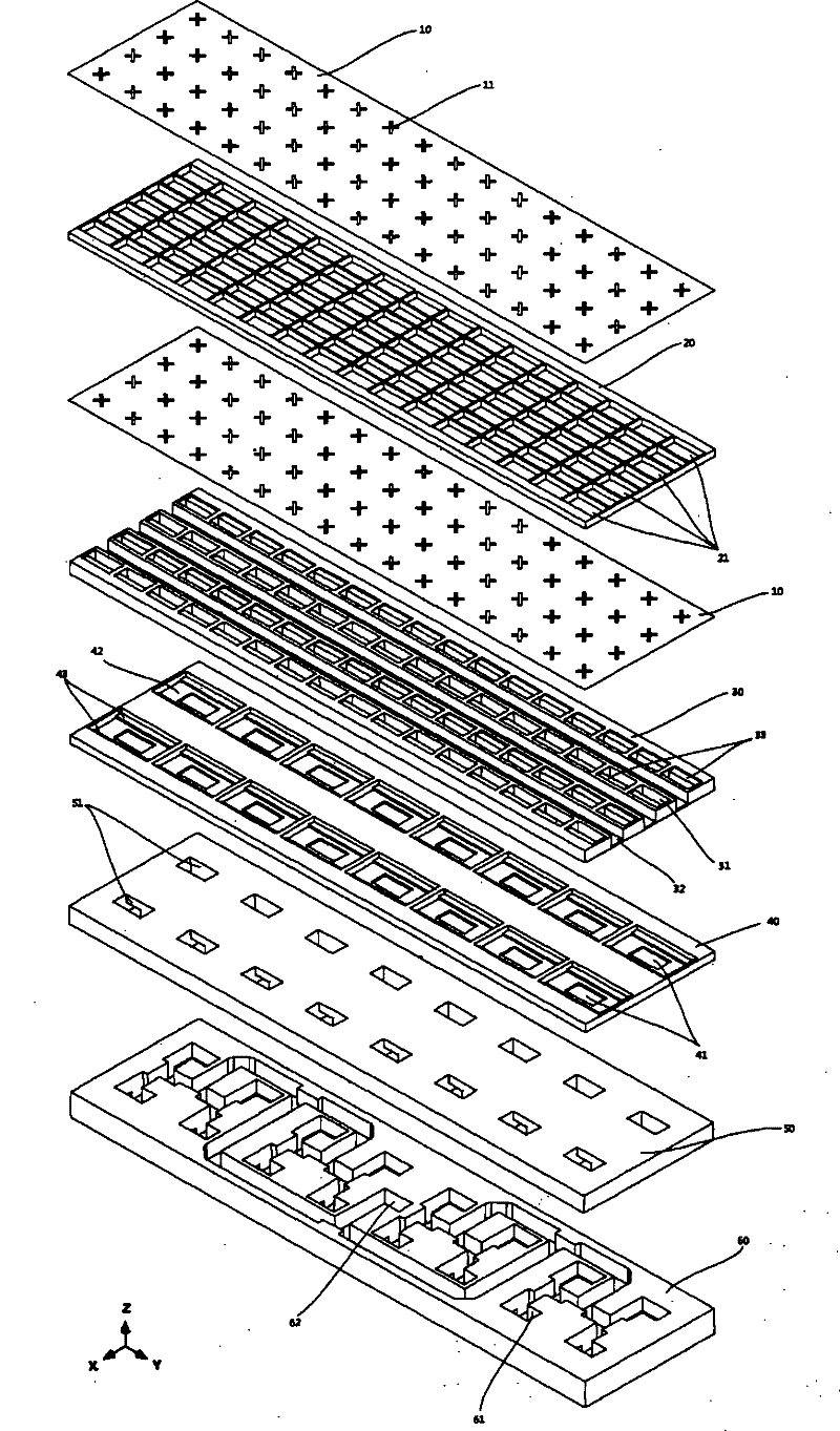
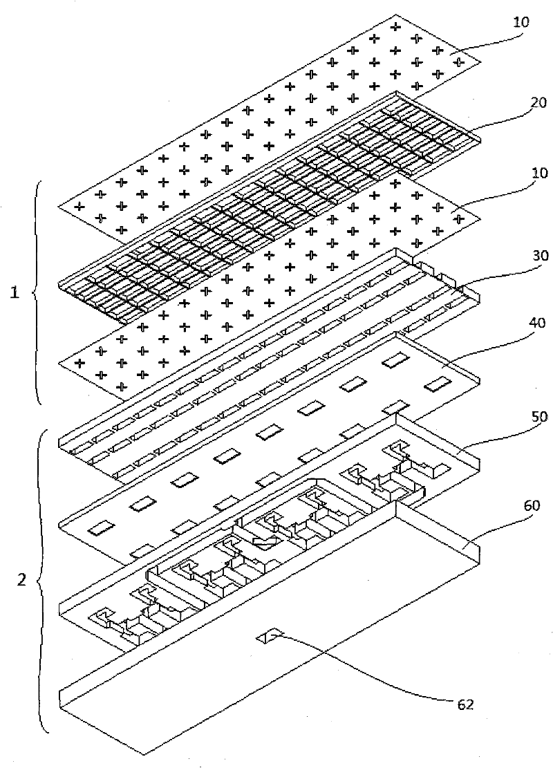
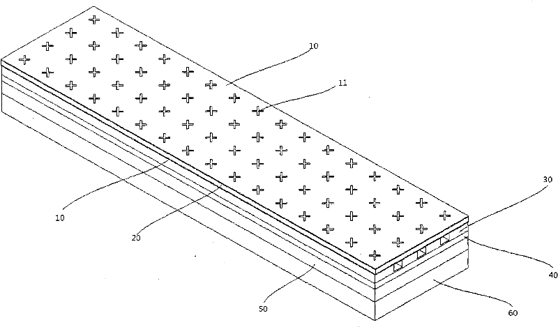
[0021] Such as figure 1 , 2 The antenna shown is composed of seven layers, which are dielectric film 10, dielectric frame 20, dielectric film 10, radiation layer 30, rectangular excitation cavity layer 40, waveguide E-T feed network upper layer 50, waveguide E-T feed network Lower level 60. The first three layers form a circular polarizer 1, and the last four layers form a waveguide plate array antenna 2. The circular polarizer 1 is stacked on the waveguide plate array antenna 2 to form a circularly polarized waveguide plate array antenna, which is located in the lower layer of the waveguide E-T feed network The input and output waveguide port 62 in the middle of 60 is the final input and output port of the signal. image 3 , 4 A circularly polarized waveguide panel array antenna formed after the above seven-layer structure is assembled is shown.

[0022] The dielectric film 10 is made by screen-printing an oblique "cross" pattern 11 with a conductive ink on PET (polyethyl...


PUM


Abstract

The invention provides a circularly polarized waveguide flat plate array antenna, which has the advantages of high antenna efficiency and low manufacturing cost. A circular polarizer is arranged on a broadband linearly polarized waveguide flat plate array antenna 2 consisting of a rectangular open-ended waveguide 31 array excited by a waveguide feed network to achieve the high circularly polarized wave receiving and transmission capability of the circularly polarized waveguide flat plate array antenna. The size of the circular polarizer 1 is completely the same as that of a radiating layer 30, and consists of two layers of completely identical dielectric thin films 10 and a dielectric bulkhead 20 made from an acrylonitrile butadiene styrene (ABS) material, wherein an inclined cross pattern 11 is screen-printed on the dielectric thin film 10 by using conductive ink. Compared with a conventional circularly polarized flat plate antenna, the circularly polarized waveguide flat plate array antenna has the characteristics of great circular polarization bandwidth, low cost and low feeder loss.

Description

technical field [0001] The invention relates to a circularly polarized waveguide plate array antenna, which has the advantages of high antenna efficiency and low manufacturing cost. Background technique [0002] Antenna gain and cost are very important indicators in satellite TV, communication and other systems. The microstrip panel antenna generally forms a feeding network by microstrip, stripline, etc., and the radiation unit usually chooses a microstrip patch, a slot, etc., and the panel antenna composed of a dielectric material, when the frequency increases (especially X~Ka Band), the feed loss increases rapidly, seriously affecting the gain. Moreover, in the application of direct broadcast satellite TV receiving antennas that require mass production, the high cost of microwave plates and etching processing costs determine that microstrip antennas are difficult to apply in this product. There are two types of waveguide slot arrays: standing wave arrays and traveling wa...

Claims


Application Information

Patent Timeline
IPC IPC(8): H01Q1/38H01Q15/24H01Q21/00
Inventor 李峰
Owner 李峰
Why Eureka
Try Eureka