Optical network unit for passive optical network and signal processing method thereof

A technology of optical network unit and passive optical network, which is applied in the field of optical network unit and its signal processing, can solve complex problems, affect the overall cost and product reliability, and change, and achieve the effect of simple structure

Inactive Publication Date: 2011-11-23
成都新易盛通信技术股份有限公司
View PDF4 Cites 14 Cited by
  • Summary
  • Abstract
  • Description
  • Claims
  • Application Information

AI Technical Summary

Problems solved by technology

The solutions in the prior art are generally dual-chip, and the peripheral components of the dual-chip are complicated, which in turn affects the overall cost and product reliability. At the same time, the APD reverse bias voltage often adopts the form of a combination of a feedback resistor and a thermistor, which cannot realize the APD voltage. Real-time control and automatic adjustment of
At present, the signal processing method of the optical network unit in the prior art has the following disadvantages: 1. If the automatic power-off is realized, the burst control signal is often directly monitored, which cannot effectively reflect the state of the laser. When the laser emits abnormal light due to internal problems in the ONU module, the laser output cannot be turned off in time; 2. The detection of the transmitted optical power can only be performed by sampling the average signal of the laser output optical power detection signal. When the module emits light under different duty ratios, the readout DDM monitoring value will change, which cannot reflect the real-time optical power output of the laser

Method used


Image

  • Optical network unit for passive optical network and signal processing method thereof
  • Optical network unit for passive optical network and signal processing method thereof
  • Optical network unit for passive optical network and signal processing method thereof

Examples


Embodiment Construction

[0034] All features disclosed in this specification, or steps in all methods or processes disclosed, may be combined in any manner, except for mutually exclusive features and / or steps.

[0035] Any feature disclosed in this specification (including any appended claims, abstract and drawings), unless expressly stated otherwise, may be replaced by alternative features which are equivalent or serve a similar purpose. That is, unless expressly stated otherwise, each feature is one example only of a series of equivalent or similar features.

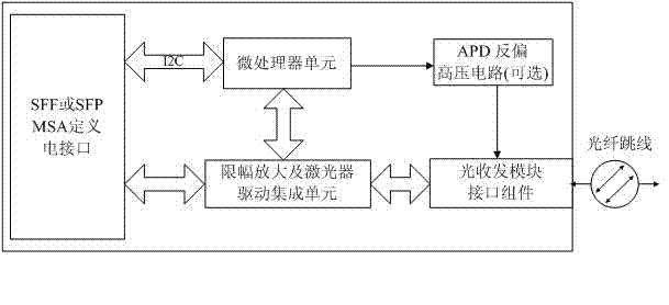
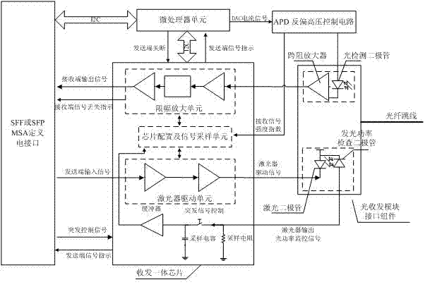
[0036] An optical network unit of a passive optical network, including an electrical interface meeting the definition of SFF or SFP, a microprocessor unit, a transceiver integrated chip, and an optical transceiver module interface assembly, the electrical interfaces are respectively connected to the microprocessor unit, the transceiver integrated chip, The above-mentioned microprocessor unit is connected to the integrated transceiver chip, and...


PUM


Abstract

The invention relates to the field of optical fiber communication and discloses an optical network unit for a passive optical network. The optical network unit comprises an electric interface meeting SFF (Small Form-factor Pluggable) or SFPMSA (Small Form-factor Pluggable Transceiver Multi-Source Agreement) definition, a microprocessor unit, an integrated transceiver chip and an optical transceiver module interface component, wherein the electric interface is respectively connected to the microprocessor unit and the integrated transceiver chip; the microprocessor unit is connected to the integrated transceiver chip; and the integrated transceiver chip is connected to the optical transceiver module interface component. The invention also discloses a signal processing method of the optical network unit for the passive optical network. A limiting amplifier unit, a laser driving unit, a chip and a signal acquiring unit are integrated in the integrated transceiver chip. The integrated transceiver chip, the microprocessor unit and a high-pressure circuit converting chip are matched with each other, thereby forming the optical network unit. The optical network unit designed according to the scheme has the characteristics of simple structure, high integrated level, low cost, suitability for large-scale automatic production, and the like.

Description

technical field [0001] The invention relates to the field of optical fiber communication, in particular to an optical network unit of a passive optical network and a signal processing method thereof. Background technique [0002] Explanation of technical terms in the text: [0003] PON (Passive Optical Network) Passive Optical Network [0004] GPON (Gigabit-Capable PON) Gigabit Passive Optical Network [0005] GEPON (Gigabit-Capable Ethernet PON) Gigabit Ethernet Passive Optical Network [0006] SFF (Small From-Factor) Miniaturized Optical Transceiver [0007] MSA (Multi-Source Agreement) multi-source agreement [0008] ONU (Optical Network Unite) Optical Network Unit [0009] OLT (Optical Line Terminal) optical cable terminal equipment [0010] PCB (Printed Circuit Board) printed circuit board [0011] LA (Limit Amplifier) ​​Limiting Amplifier [0012] LDD (Laser Diode Driver) laser diode driver [0013] ADC (Analog to Digital Converter) analog to digital conversio...

Claims


Application Information

Patent Timeline
Patent Type & Authority Applications(China)
IPC IPC(8): H04B10/08H04B10/155H04B10/17H04B10/25H04B10/40
Inventor 陈钢黄晓雷宛明赵家闯曹阳
Owner 成都新易盛通信技术股份有限公司
Why Eureka
Try Eureka