Inverter generator

A technology for inverters and generators, which is applied to the control of generators, motors, and AC motors. The effect of high speed

Inactive Publication Date: 2011-11-23
SAWAFUJI ELECTRIC COMPANY
View PDF6 Cites 6 Cited by
  • Summary
  • Abstract
  • Description
  • Claims
  • Application Information

AI Technical Summary

Problems solved by technology

[0008] In this case, for example, a large load is connected to only one of the two inverter units, and the load imbalance of the inverter units occurs.
In addition, one of the loads connected to each inverter unit is an inductive load and the other is a capacitive load.
According to the nature of such a load, the output voltage-output current characteristics are different from each other, but even so, it is desirable to set the output voltage-output current characteristics to be flat
[0009] In addition, generally speaking, when the load connected to the power supply line is small, the engine speed is kept low to suppress noise generation. However, for example, when an electric motor is connected and started as a load, In the form where a large starting current flows, the engine speed should increase along with the start, but there is a problem that the engine speed increase becomes slow

Method used


Image

  • Inverter generator
  • Inverter generator
  • Inverter generator

Examples


Embodiment Construction

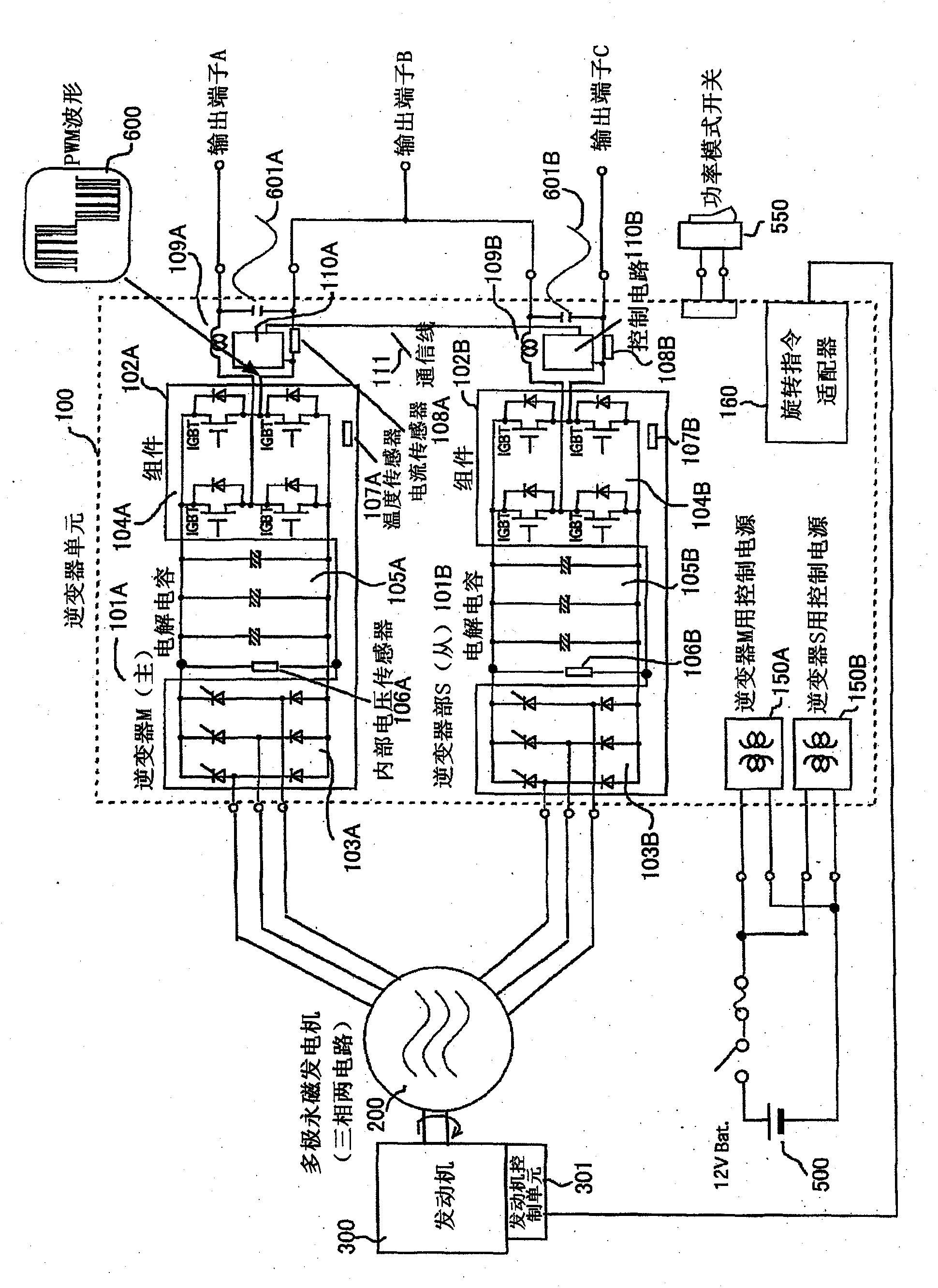
[0080] figure 1 This shows the structure of one embodiment of the present invention.

[0081] The number 100 in the figure is an inverter unit, 200 is a multi-pole permanent magnet generator (Parmanent Magnet Alternator-PMA), 300 is an engine, 500 is a power supply for inverter control, and 550 is a power mode switch indicating the operation mode. unit.

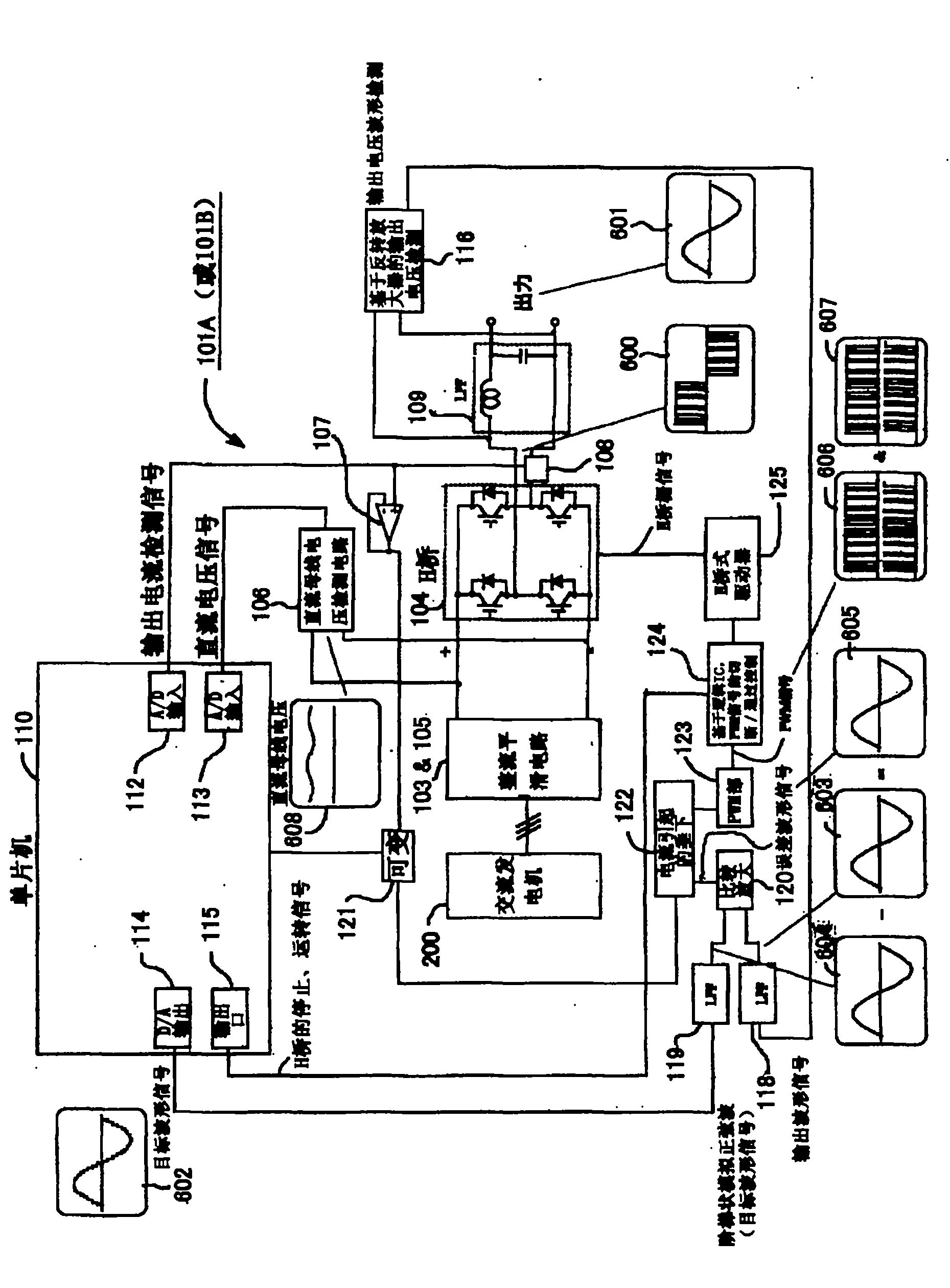
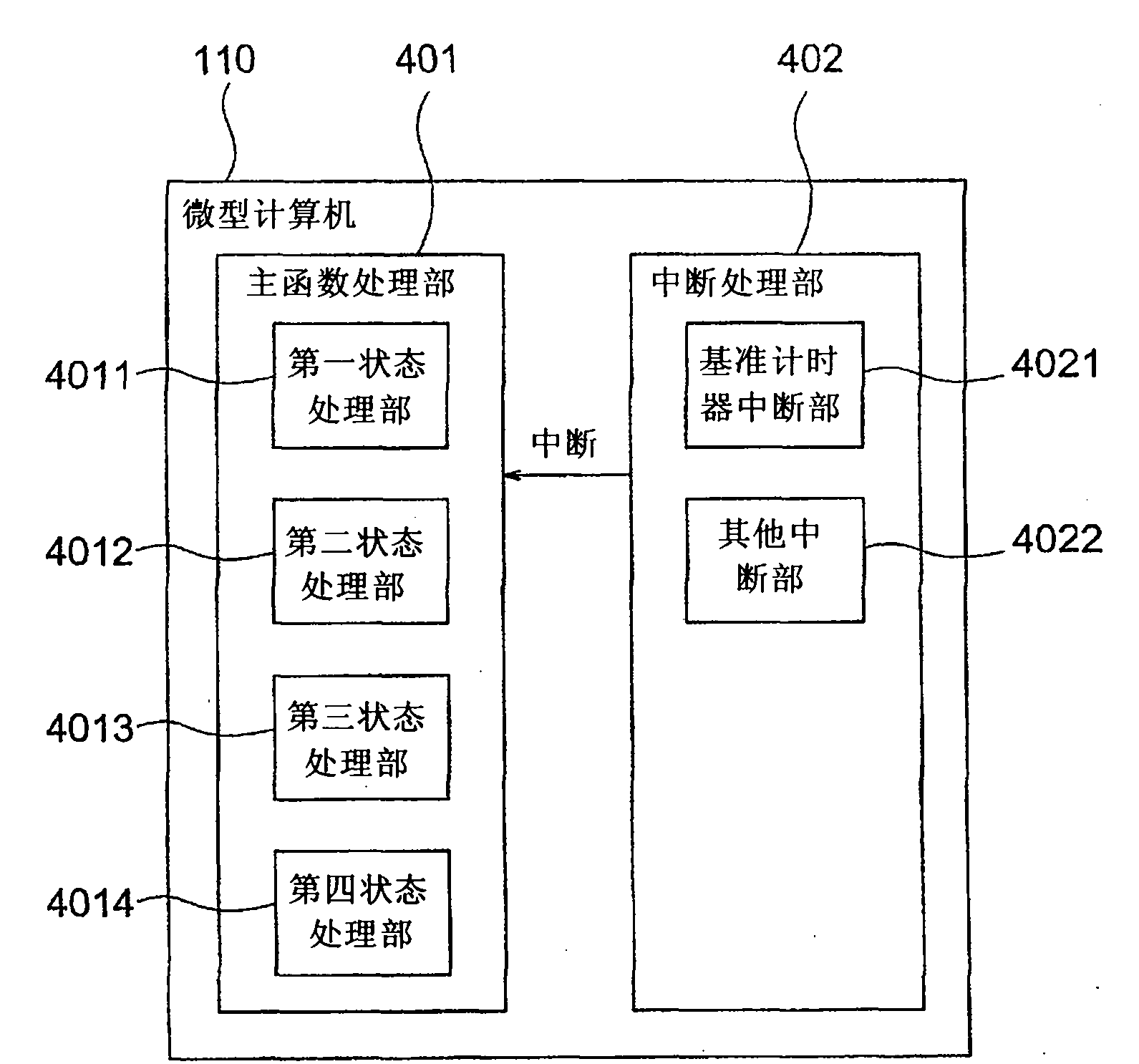
[0082] 101 is an inverter unit, 102 is an inverter module, 103 is a rectifier circuit unit, 104 is an inverter circuit unit (H bridge), 105 is an electrolytic capacitor unit, and 106 is an internal voltage sensor that constitutes a DC bus that will be described later. The unit of the voltage detection circuit, 107 is a temperature sensor, 108 is a current sensor, 109 is a smoothing filter unit, 110 is a unit composed of a single-chip computer as a control circuit, 111 is a communication line and a unit for sending and receiving information between the control circuits 110A and 110B , 150 is an inverter control power supply,...


PUM


Abstract

Each of two inverter units has a control circuit (microcomputer). The intensity of a target waveform signal corresponding to a voltage to be outputted from each of the inverter units is successively determined by considering the effective power and the ineffective power outputted from each of the inverter units. By performing communication between the control circuits, the phases of the two inverter units are matched with each other so as to prevent output shortage of an engine or an AC generator by an abrupt load increase.

Description

technical field [0001] The present invention relates to an inverter generator in which an engine-driven generator is connected to an inverter unit, and the output of a smoothing filter connected to the inverter unit is connected in series, that is, a so-called single-phase three-wire generator. powered by. Background technique [0002] Conventionally, an inverter unit is connected to an engine-driven generator, and a predetermined AC voltage is fed at a predetermined frequency. Furthermore, the outputs of the plurality of inverter units are connected in parallel and supplied to the load. [0003] When the inverter units are connected in parallel in this way, for example, the output voltages of the two inverter units are controlled to be the same. Also, in this case, if the output frequencies of the two inverters deviate, the effective power shared between the two inverters will differ. In addition, if the output voltage varies, reactive power may circulate between the inv...

Claims


Application Information

Patent Timeline
Patent Type & Authority Applications(China)
IPC IPC(8): H02P9/04
CPCH02P27/08H02P9/48H02P2009/002H02P2207/076H02P2101/45
Inventor 生井正夫吉冈徹我妻真一柄沢幸雄
Owner SAWAFUJI ELECTRIC COMPANY
Why Eureka
Try Eureka