An energy-saving device for directional solidification and impurity removal of metallurgical silicon

A directional solidification and energy-saving device technology, applied in silicon compounds, non-metallic elements, inorganic chemistry, etc., can solve the problems of long production cycle, high equipment cost, and silicon leakage accidents of quartz ceramics, so as to reduce the amount of auxiliary materials and improve repeatability. The number of times of use and the effect of strong heat storage capacity

Active Publication Date: 2011-11-30
宁夏高创特能源科技有限公司
View PDF7 Cites 10 Cited by
  • Summary
  • Abstract
  • Description
  • Claims
  • Application Information

AI Technical Summary

Problems solved by technology

Invention patents CN85100519 "A polycrystalline silicon ingot process for directional solidification and growth of solar cells", CN101323972 "A device for directional solidification of polycrystalline silicon", CN101898763 "A method for preparing directional solidification polycrystalline silicon", CN85100529 "A kind of directional solidification growth Polysilicon Ingot Process for Solar Cells" and so on, these published patent applications are all inventions for solar cell polysilicon ingot casting process and equipment similar to polysilicon ingot furnace, because such equipment requires vacuum system, heating system, measuring Temperature systems, etc., need to remelt silicon materials in the equipment, so the equipment has the disadvantages of high cost, long production cycle, and large energy consumption for monomer solidification.
The quality of metallurgical silicon (2N grade) is 3 to 4 orders of magnitude lower than that of crystalline silicon (5 to 6N), and the impurity content is high. If the polysilicon ingot furnace is directly used for directional solidification, it will cause rapid aging of the graphite parts of the ingot furnace, and the quartz ceramic crucible The high cost of polysilicon ingot casting furnace is not suitable for metallurgical silicon directional solidification requirements

Method used


Image

  • An energy-saving device for directional solidification and impurity removal of metallurgical silicon
  • An energy-saving device for directional solidification and impurity removal of metallurgical silicon
  • An energy-saving device for directional solidification and impurity removal of metallurgical silicon

Examples


specific Embodiment approach

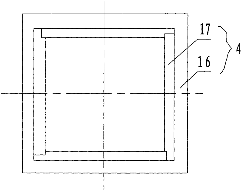
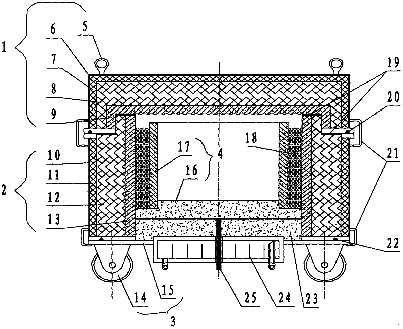
[0021] Such as figure 1 and figure 2 As shown, the device is a rectangular body, including an upper insulation cover (1), a middle insulation cover (2) and a lower floor rail frame (3), a composite mold (4), a heat conducting plate (23) and a water-cooled copper plate (24 ), the water-cooled copper plate (24) is located in the middle of the lower floor track frame (3), the heat conduction plate (23) is located on the top of the water-cooled copper plate (24), and the composite mold (4) is arranged on the heat conduction plate (23) In the upper part, silicon carbide particles (18) are filled around the composite mold (4) for support and heat preservation, and a sealing ring (20) is arranged between the upper heat preservation cover (1) and the middle heat preservation cover (2).

[0022] The upper insulation cover (1) includes a suspension ring (5), a steel furnace cover (6), a polycrystalline ceramic fiber layer (7), a potassium hexatitanate whisker layer (8), and a corundum...


PUM


Abstract

The invention relates to an energy saving device for the directional solidification and impurity removal of metallurgical silicon. The device is a rectangular body and comprises an upper heat preservation cover, a middle heat preservation sleeve, a lower bottom plate rail frame, a composite die, a heat conducting plate and a water-cooled copper disc, wherein the water-cooled copper disc is arranged in the middle of the lower bottom plate rail frame; the heat conducting plate is arranged on the upper part of the water-cooled copper disc; the composite die is arranged on the upper part of the heat conducting plate; the periphery of the composite die is filled with silicon carbide particles with supporting and heat preservation effects; and a sealing ring is arranged between the upper heat preservation cover and the middle heat preservation sleeve. The device is suitable for the directional solidification and non-vacuum production of the metallurgical silicon by a casting method, has lowmanufacturing cost and energy consumption and small maintenance amount, is conveniently and safely used, and is environment-friendly, directional solidification and purification effects are achieved by a simple device, product quality is improved, and production cost is reduced.

Description

technical field [0001] The invention belongs to the technical field of polysilicon purification by metallurgical methods, and in particular relates to an energy-saving device for directional solidification and impurity removal of metallurgical silicon. Background technique [0002] In order to further improve the quality of metallurgical silicon, domestic and foreign enterprises have adopted various methods and measures, such as: selecting optimal raw materials, blowing chlorine outside the furnace, refining with oxygen blowing, adding solvents, directional solidification, etc., and achieved great results in removing various impurities. good effect. Among them, the directional solidification process is an important part of the metallurgical preparation of solar-grade polysilicon. It makes the silicon ingot grow unidirectionally by controlling the temperature field change, and uses the segregation effect to separate the main metal impurity elements Fe, Al, Ca, Ti, Cu, Zn, Mn...

Claims


Application Information

Patent Timeline
IPC IPC(8): C01B33/037
Inventor 刘应宽盛之林刘永贵范占军纳永清李小燕
Owner 宁夏高创特能源科技有限公司
Why Eureka
Try Eureka