A method for repairing micro-polluted water body and subsurface flow constructed wetland system

A constructed wetland system and micro-pollution technology, applied in chemical instruments and methods, multi-stage water/sewage treatment, water/sludge/sewage treatment, etc., can solve the problem of smooth surface that is not conducive to microbial attachment and growth, nitrogen and phosphorus pollutants Low removal rate, limited pollutant removal effect, etc., to achieve the effect of strong impact load resistance, low wetland resistance, and not easy to clog

Inactive Publication Date: 2011-12-14
CHONGQING UNIV
View PDF7 Cites 18 Cited by
  • Summary
  • Abstract
  • Description
  • Claims
  • Application Information

AI Technical Summary

Problems solved by technology

[0006] However, there are some deficiencies in the treatment of slightly polluted water by constructed wetlands: ① Low hydraulic load: Under high hydraulic load, the effect of constructed wetlands on pollutant removal is very limited. Generally speaking, in order to achieve a better treatment effect, it should be kept low. hydraulic load
②Low removal rate of nitrogen and phosphorus pollutants: At present, most of the constructed wetlands that treat slightly polluted water bodies use canna, reed, calamus, etc. as wetland plants, and gravel, pebbles, gravel, etc. , 30%~50% on average
④Fillers are easy to saturate: wetland fillers such as crushed stones, pebbles and gravels have low saturated adsorption capacity, and their smooth surfaces are not conducive to the attachment and growth of microorganisms
Therefore, a large number of research results have found that the treatment effect of constructed wetlands is often high in the initial stage of operation, and as the treatment time increases, the treatment effect gradually declines

Method used


Image

  • A method for repairing micro-polluted water body and subsurface flow constructed wetland system
  • A method for repairing micro-polluted water body and subsurface flow constructed wetland system
  • A method for repairing micro-polluted water body and subsurface flow constructed wetland system

Examples


example

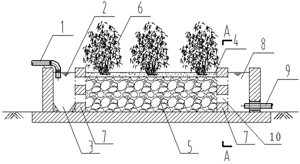
[0046] Example: The present invention is applied to the water treatment of a slightly polluted river, which is the main supply river of the local drinking water source. The improved subsurface flow artificial wetland of "Luzhu-Shale Brick" is built in the open area near the end of the river. 0.9m), the bottom slope is 2%. The Reed Bamboo Wetland is divided into water inlet area, wetland bed and water outlet area. The water inlet area is 0.5m long, 1.0m wide, and 1.0m high. . The wetland bed is 3.0m long, 1.0m wide, 1.0m high and 0.1m super high. The filling system of wet bed bed is 20cm shale bricks (particle size 40~60mm), 30cm shale bricks (particle size 20~40mm), 30cm shale bricks (particle size 10~20mm) and 10cm gravel (particle size) from bottom to top. diameter 5~10mm). Wetland plants use reed bamboo, and the planting density is 10~20 plants / m 2 . A water outlet area is set at the end of the wetland, with a length of 0.5m, a width of 1.0m and a height of 1.0m, and ...


PUM

PropertyMeasurementUnit
particle diameteraaaaaaaaaa
heightaaaaaaaaaa

Abstract

The invention discloses a method for remedying the micro-polluted water body. The method comprises the following steps: 1) the micro-polluted water body firstly enters a first-stage water treatment area to perform sand settling and uniform water distribution; 2) the water body secondly enters a second-stage water treatment area-wetland bed, wherein the wetland bed is mainly composed of filler anda water plant, the water plant is giant reed, the filler is composed of upper filler and lower filler, the upper filler is gravel and the particle size is 5-10mm; the lower filler is the shale brick,the particle size of the shale brick is 10-60mm and the root system of the water plant grows in the filler; and 3) the water body finally enters a third-stage water treatment area to homogenize the effluent quality, and the water body can be discharged and enter the outer water body. The system has the following advantages: (1) no energy is consumed, the system is difficult to block; (2) the investment is low, the system is convenient to operate and manage; (3) the shock resistance is strong; and (4) the nitrogen-phosphorus removal rate is high and the system has a certain economic benefit.

Description

technical field [0001] The invention relates to a method for repairing polluted water bodies and the corresponding improved subsurface flow constructed wetland system of "Luzhu-shale bricks" for repairing polluted water bodies. field of environmental engineering. [0002] Background technique [0003] Slightly polluted source water refers to water bodies that are polluted by organic matter, and some water quality indicators exceed the standard for Class III water bodies in the "Environmental Quality Standards for Surface Water" (GB3838-2002). Slightly polluted water is generally caused by the sewage generated in industry, agriculture and life without proper treatment and directly discharged into water supply sources. Slightly polluted water mainly contains harmful pollutants such as particulate matter, trace organic matter, pesticides, and ammonia nitrogen. Micro-pollutants in slightly polluted water have the characteristics of large pollution range and wide influence ran...

Claims


Application Information

Patent Timeline
Patent Type & Authority Applications(China)
IPC IPC(8): C02F9/14
CPCY02A40/22
Inventor 黄磊高旭郭劲松谢伟丹马晓霞刘明
Owner CHONGQING UNIV
Why Eureka
Try Eureka