Dissolving heat absorption type chemical heat pump and heating or refrigerating method thereof

A chemical heat pump and heat-absorbing technology, which is applied in energy-saving heating/cooling, refrigerators, adsorption machines, etc., can solve the problem of inability to form high-temperature areas at the bottom, exothermic areas, bottom-temperature areas, working fluids that cannot be reliably circulated, and that cannot be exchanged Heat and other issues

Active Publication Date: 2013-01-02
江苏河海新能源技术发展有限公司
View PDF6 Cites 0 Cited by
  • Summary
  • Abstract
  • Description
  • Claims
  • Application Information

AI Technical Summary

Problems solved by technology

However, since the high-temperature and high-concentration ammonium nitrate solution is located at the bottom of the tower, while the low-temperature and low-concentration solution is located at the top of the tower, on the one hand, the low-temperature and low-concentration ammonium nitrate solution at the top of the tower is difficult to freely dissolve and mix with the high-temperature and high-concentration ammonium nitrate solution at the bottom , resulting in the working medium not being able to circulate reliably to achieve the effect of heat exchange
On the other hand, since the heater heats the ammonium nitrate solution at the bottom of the tower, the heated ammonium nitrate solution will generate a certain amount of water vapor after being concentrated, and the high-temperature water vapor will move to the middle and upper parts of the tower body, so the inside of the tower It is impossible to form a high-temperature zone at the bottom, an exothermic zone in the middle and a low-temperature zone at the top, and heat exchange is actually impossible

Method used


Image

  • Dissolving heat absorption type chemical heat pump and heating or refrigerating method thereof

Examples


Embodiment Construction

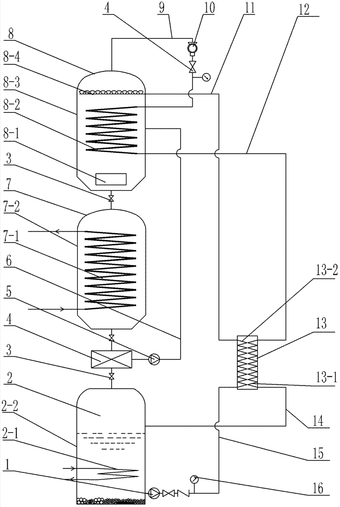
[0011] See figure 1 As shown, the dissolution endothermic chemical heat pump of the present invention includes an evaporator 2, a condenser 7, a reactor 8, an air compressor 10, a solid-liquid separator 4, and a circulation heat exchanger 13, and the circulation heat exchanger 13 is a conventional The plate heat exchanger, the present invention uses ammonium nitrate aqueous solution as the working medium, the evaporator 2 includes the evaporation container 2-2 and the cold end heat exchange tube 2-1 arranged in the evaporation container 2-2, the cold end heat exchange tube 2 -1 communicates with the cold-end user medium through the pipeline, so that the cold-end user medium can circulate in the cold-end heat exchange tube 2-1 for heat exchange, and the mass concentration in the evaporation container 2-2 of the present invention is 47% to 54% % ammonium nitrate aqueous solution, which is liquid ammonium nitrate working medium and solid ammonium nitrate working medium. The tempe...


PUM


Abstract

The invention relates to a dissolving heat absorption type chemical heat pump which comprises an evaporator, a condenser, a reactor, an air compressor as well as a solid-liquid separator and a circulating heat exchanger, wherein the cold-end heat exchange pipe of the evaporator is communicated with cold-end user media by virtue of a pipeline; a conveying pipe connected with the evaporator is communicated with more than two liquid distribution pipes arranged on the upper part of the reactor by virtue of a warming pipe of the circulating heat exchanger and a conveying coupling pipe, and a plurality of liquid outlets are arranged on each liquid distribution pipe; a vapor pipe arranged on the top of the reactor and a cooling pipe of the circulating heat exchanger are communicated by virtue ofthe air compressor, the heat exchange pipe arranged in the reactor and a backflow coupling pipe; a hot-end heat exchange pipe arranged in the condenser is communicated with hot-end user media, and the lower part of the reactor is communicated with the condenser; and the solid-liquid separator is arranged between the condenser and the evaporator, and a return liquid port of the solid-liquid separator is communicated with the reactor by virtue of a return liquid pipe. The chemical heat pump provided by the invention has the advantages of simple structure, stable heat exchange efficiency, and low use-cost.

Description

technical field [0001] The invention relates to a dissolving heat-absorbing chemical heat pump and a heating or cooling method thereof, and belongs to the technical field of heat pumps using dissolved substances for heat exchange. Background technique [0002] The chemical heat pump system utilizes the conversion of thermal energy and chemical energy in the reversible reaction in chemical reactions to realize cooling, heating and other functions. Usually, during the desorption process, the solid reactor absorbs heat, and the adsorbent desorbs the refrigerant gas under high pressure. The refrigerant gas enters the condenser to condense and release heat, and then enters the evaporator through the throttle valve, and the refrigerant gas evaporates in the evaporator. , to produce a cooling effect on the outside world. On the other hand, the refrigerant gas evaporated at a lower pressure is adsorbed by the adsorbent to release heat, so that through such a cycle, the effect of co...

Claims


Application Information

Patent Timeline
Patent Type & Authority Patents(China)
IPC IPC(8): F25B15/02
CPCY02B30/62Y02A30/27
Inventor 杨家华荆国政朱庭浩
Owner 江苏河海新能源技术发展有限公司
Why Eureka
Try Eureka