
Temperature Compensation Circuit of Rectifier Diode in Flyback Converter

A technology of flyback converter and temperature compensation circuit, which is applied in the direction of converting DC power input to DC power output, instruments, electrical components, etc. Small chip area, improved integration, and increased reusability

Inactive Publication Date: 2011-12-21
XIDIAN UNIV
View PDF4 Cites 38 Cited by
  • Summary
  • Abstract
  • Description
  • Claims
  • Application Information

AI Technical Summary

Problems solved by technology

[0012] In actual circuit design, due to the forward voltage drop V of the rectifier diode D1 on the secondary side of the flyback converter F has a negative temperature characteristic, that is, V F decreases with increasing temperature, so that figure 2 The middle output voltage sampling point A moves down along the curve, so that the actual output voltage sampling value decreases. After being adjusted by the peak current mode control circuit, the output voltage Vo of the flyback converter will become higher, deviate from the design value, and be too high The output voltage of the output voltage will also have an impact on the circuit of the subsequent stage. For example, the output voltage that is too high will start the overvoltage protection circuit in the circuit of the subsequent stage, so that the circuit of the latter stage will not work.

Method used


Image

  • Temperature Compensation Circuit of Rectifier Diode in Flyback Converter
  • Temperature Compensation Circuit of Rectifier Diode in Flyback Converter
  • Temperature Compensation Circuit of Rectifier Diode in Flyback Converter

Examples


Embodiment Construction

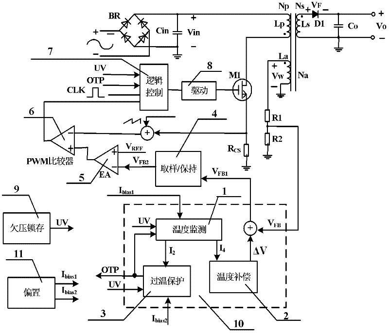
[0031] refer to image 3 , the primary side feedback flyback converter with the rectifier diode temperature compensation circuit of the present invention is mainly composed of a rectifier bridge BR, an input capacitor Cin and an output capacitor Co, a transformer primary side coil Lp with a number of turns Np, and a secondary side coil Ls, Its number of turns is Ns, auxiliary winding La, its number of turns is Na, secondary side rectifier diode D1, resistors R1 and R2, rectifier diode temperature compensation circuit 10, undervoltage lockout module 9, bias module 11, sample / hold Module 4, error amplifier EA5, PWM comparator 6, logic control module 7, drive module 8, power tube M1, and current sampling resistor R CS Composition; the undervoltage lockout module 9 outputs the undervoltage protection signal UV to the logic control module 7 and the rectifier diode temperature compensation circuit 10; the bias module 11 generates two constant bias currents I bias1 and I bias2 Inpu...


PUM


Abstract

The invention discloses a rectifier diode temperature compensation circuit in a flyback converter, which mainly solves the problem that as the temperature rises, the forward voltage drop of the secondary side rectifier diode of the primary side feedback flyback converter is decreased to cause the increase of the output voltage of the flyback converter. The circuit comprises a temperature monitoring module, a temperature compensation module and an overtemperature protection module; the temperature monitoring module monitors the change of temperature, and respectively outputs two routes of current changing along with the temperature to the temperature compensation module and the overtemperature protection module; the temperature compensation module adds the generated compensation value intothe feedback voltage of the flyback converter, and outputs the compensated feedback voltage; and the overtemperature protection module carries out overtemperature protection by way of current comparison. The circuit not only can compensate the change of the forward voltage drop of the secondary side rectifier diode of the flyback converter as the temperature changes, but also can provide overtemperature protection for the flyback converter, moreover, the circuit structure is simple, and the circuit can be used in the designs of AC / DC (alternating current-to-direct current) conversion controller chips adopting the primary side feedback control technology.

Description

technical field [0001] The invention belongs to the technical field of electronic circuits and relates to an analog integrated circuit, in particular to a rectifier diode temperature compensation circuit in a flyback converter, which can be used in the design of a flyback conversion control chip using primary side feedback control. Background technique [0002] In switching power supply circuits, high-voltage and high-current power switching circuits are often integrated, which will generate a lot of power consumption. With the increase of power consumption, the temperature of the circuit will also rise, so that the temperature-sensitive triode in the circuit Some characteristic parameters of devices such as diodes and diodes will also change, such as the base-emitter voltage V of bipolar transistors BE And the forward voltage drop of the diode will decrease with the increase of temperature, thus affecting the normal operation of the circuit. [0003] The flyback converter ...

Claims


Application Information

Patent Timeline
IPC IPC(8): H02M3/335
Inventor 叶强来新泉畅彦君王松林赵永瑞
Owner XIDIAN UNIV
Features
  • Generate Ideas
  • Intellectual Property
  • Life Sciences
  • Materials
  • Tech Scout
  • Unparalleled Data Quality
  • Higher Quality Content
  • 60% Fewer Hallucinations
Learn More