A large field of view wide spectral line lithography projection objective lens
A technology of lithographic projection and objective lens, which is applied in the field of semiconductors, can solve problems such as complex structures, and achieve the effect of high yield and simple structure
- Summary
- Abstract
- Description
- Claims
- Application Information
AI Technical Summary
Problems solved by technology
Method used
Image

Examples
Embodiment 1
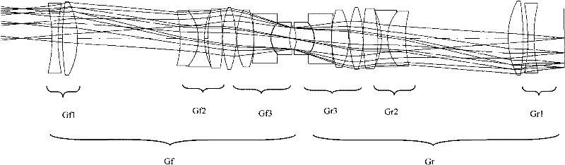
[0063] figure 1 It is a structural diagram of the first embodiment of the lithography projection objective lens of the present invention, including 18 lenses, all of which are spherical lenses. The applicable spectrum is a wide spectral band including g-line, h-line and i-line, providing a field of view of 200mm and a magnification of -1.
[0064] As shown in the figure, the first, second and third lens groups in front of the diaphragm constitute the front group lens Gf. The first lens group Gf1 consists of a biconcave lens and a biconvex lens. The second lens group Gf2 is composed of a meniscus lens, a biconcave lens and a biconvex lens, and the meniscus lens is bent toward the mask direction. The third lens group Gf3 consists of a biconvex lens, a biconvex lens, a biconcave lens, and a meniscus lens.
[0065]The rear group is symmetrical about the aperture with respect to the front group.
[0066] The focal length of the first lens group Gf1 in the front group Gf is posi...
Embodiment 2
[0088] Figure 4 It is a structural diagram of the second embodiment of the lithography projection objective lens of the present invention. As shown, the system contains 18 lenses, all of which are spherical lenses. The applicable spectrum is a wide spectral band including g-line, h-line and i-line, providing a field of view of 200mm and a magnification of -1.
[0089] As shown in the figure, the first lens group Gf1 in the front group Gf is composed of a biconcave lens, a meniscus lens and a meniscus lens, and the meniscus lens is bent toward the mask direction; the second lens group in the front group Gf Gf2 is made up of a double-concave lens and a double-convex lens, and the third lens group Gf3 in the front group Gf is made up of a double-convex lens, a double-convex lens, a double-concave lens, a meniscus lens, and the concave surface of the meniscus lens faces the diaphragm;
[0090] The rear group Gr is symmetrical about the aperture with respect to the front group G...
Embodiment 3
[0112] Figure 7 It is a structural diagram of the third embodiment of the lithography projection objective lens of the present invention, including 16 lenses, all of which are spherical lenses. The applicable spectrum is a wide spectral band including g-line, h-line and i-line, providing a field of view of 200mm and a magnification of -1.
[0113] As shown in the figure, the first lens group Gf1 is composed of a biconcave lens and a biconvex lens. In addition, the second lens group Gf2 in the front group Gf consists of a biconcave lens and a biconvex lens. The third lens group Gf3 in the front group Gf consists of a biconvex lens, a biconvex lens, a biconcave lens, and a meniscus lens, and the meniscus lens is bent towards the diaphragm.
[0114] The rear group Gr is symmetrical about the aperture with respect to the front group Gf.
[0115] The focal length of the first lens group Gf1 in the front group Gf is positive and relatively large, which is mainly conducive to the...
PUM
| Property | Measurement | Unit |
|---|---|---|
| Field of view | aaaaa | aaaaa |
Abstract
Description
Claims
Application Information
 - Generate Ideas
- Intellectual Property
- Life Sciences
- Materials
- Tech Scout
- Unparalleled Data Quality
- Higher Quality Content
- 60% Fewer Hallucinations
Browse by: Latest US Patents, China's latest patents, Technical Efficacy Thesaurus, Application Domain, Technology Topic, Popular Technical Reports.
© 2025 PatSnap. All rights reserved.Legal|Privacy policy|Modern Slavery Act Transparency Statement|Sitemap|About US| Contact US: help@patsnap.com