
Carbonation calcination reaction process for CO2 capture using a highly regenerable sorbent

一种吸附剂、碳酸化的技术,应用在化学仪器和方法、分离方法、通过吸附等方向,能够解决吸附剂反应性稳定下降等问题

Active Publication Date: 2012-01-04
THE OHIO STATE UNIV RES FOUND
View PDF5 Cites 19 Cited by
  • Summary
  • Abstract
  • Description
  • Claims
  • Application Information

AI Technical Summary

Problems solved by technology

Although this method was found to reduce sintering and reactivate the sorbent, a steady decrease in the reactivity of the sorbent was still observed

Method used


Image

  • Carbonation calcination reaction process for CO2 capture using a highly regenerable sorbent
  • Carbonation calcination reaction process for CO2 capture using a highly regenerable sorbent
  • Carbonation calcination reaction process for CO2 capture using a highly regenerable sorbent

Examples


Embodiment Construction

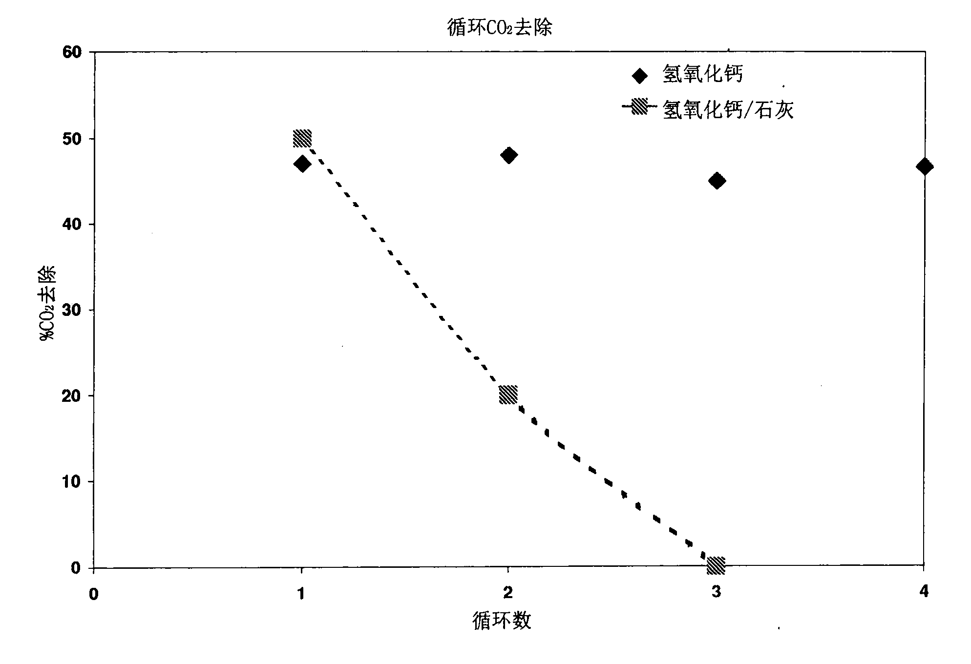
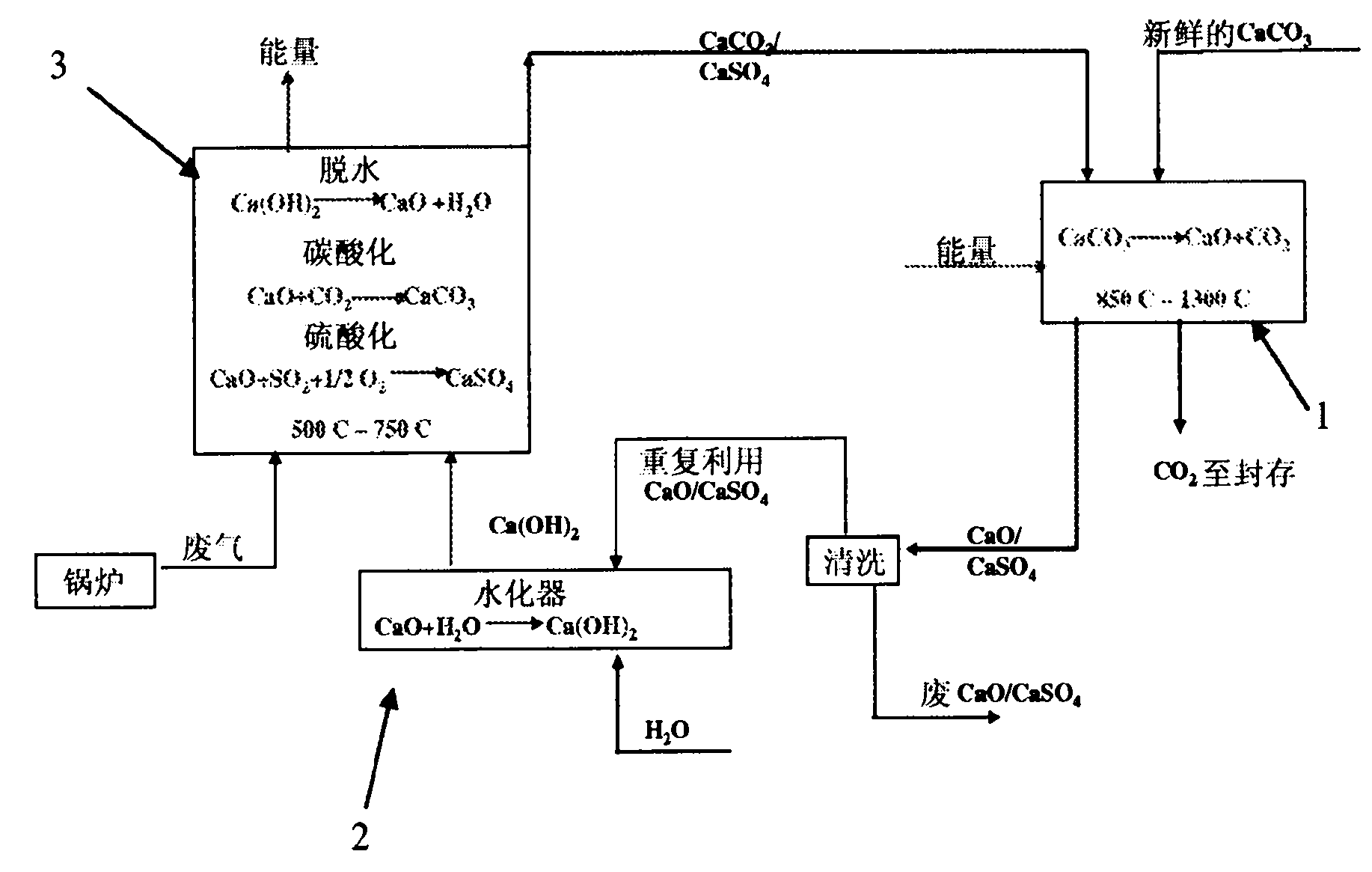
[0039] The regenerability of calcium oxide sorbent is high temperature calcium-based CO 2 The main disadvantage of the capture method. A potential solution is to hydrate the sorbent with ambient water during each cycle, which leads to a complete reactivation of the sorbent. However, due to the capture of CO 2 High-quality heat was previously required for dehydration of sorbents, and this ambient-temperature reactivation technique results in very high additional energy consumption. To this end, exemplary embodiments provide a unique method of pressure hydration for reactivating the sorbent without adding additional energy to the overall process. The pressure hydration of high calcium content oxides is performed at or above the temperature used for the dehydration reaction to enhance the quality of the heat of hydration (e.g., at about 300 psi, the hydration temperature is about 600° C.) and to allow This energy can be used for dehydration reactions. figure 1 Provides for CO...


PUM


Abstract

A process for the efficient capture of CO2 and sulfur from combustion flue gas streams and gasification based fuel gas mixtures using regenerable and recyclable calcium based sorbents. The regeneration of the calcium sorbent is accomplished by hydrating the sorbent at high temperatures of about 600 DEG C and a pressure higher than 6 bars to lower the parasitic energy consumption.

Description

[0001] Cross References to Related Applications [0002] This application claims priority to US Provisional Patent Application No. 61 / 116,172, filed November 19, 2008, the entire contents of which are hereby incorporated by reference. technical field [0003] Exemplary embodiments relate to the removal of pollutants from an exhaust gas stream. More specifically, exemplary embodiments relate to the reactivation of sorbents used to remove pollutants from exhaust gas streams. Background technique [0004] The concept of using lime to capture carbon dioxide has been around for over a century. It was first proposed by DuMotay and Marechal in 1869 for the enhanced gasification of coal using lime, and a century later by CONSOL's CO 2 receiver approach, the concept was tested in a 40 t / day plant. A variant of this method, called the Hypring method, was developed in Japan to produce hydrogen at high pressure. Harrison et al. and Grace et al. also applied the concept to the produc...

Claims


Application Information

Patent Timeline
Patent Type & Authority Applications(China)
IPC IPC(8): B01D53/14B01D53/02F02M35/00B01D53/62
CPCY02C10/08B01J20/3491B01J20/043B01J20/041B01J20/3433C01F11/02B01D53/96Y02C10/04B01D2257/302B01D2257/504B01J20/3483Y02C10/06B01D2251/404B01D53/508B01D53/62Y02P20/129Y02C20/40Y02P20/151
Inventor 梁诗·范S·拉姆库玛儿W·王R·斯达尼克
Owner THE OHIO STATE UNIV RES FOUND
Learn More