
Lithium ion flow redox battery

A flow battery, lithium ion technology, applied in battery electrodes, regenerative fuel cells, circuits, etc., can solve the problems of hindering the large-scale application of power grid energy storage systems, polluting river water and groundwater, and high operating temperature range, and achieve battery volume energy density and The effect of increased mass energy density, less corrosiveness, and wider operating temperature range

Inactive Publication Date: 2012-01-11
BEIJING HAWAGA POWER STORAGE TECH +1
View PDF3 Cites 58 Cited by
  • Summary
  • Abstract
  • Description
  • Claims
  • Application Information

AI Technical Summary

Problems solved by technology

However, there are serious defects in all-vanadium redox flow batteries: the electrolyte of all-vanadium redox flow batteries will produce waste gas, dust and waste water during the manufacturing process, especially the improper treatment of vanadium-containing sulfuric acid waste liquid may pollute river water or groundwater, forming an environment Pollution
Although it has the characteristics of high voltage, large specific energy, long cycle life, no memory, low pollution, and high operating temperature range, the cost and safety of large-capacity lithium-ion batteries have always been a prominent problem, hindering its use as a power grid. Large-scale application of energy storage system

Method used


Image

  • Lithium ion flow redox battery
  • Lithium ion flow redox battery
  • Lithium ion flow redox battery

Examples


Embodiment Construction

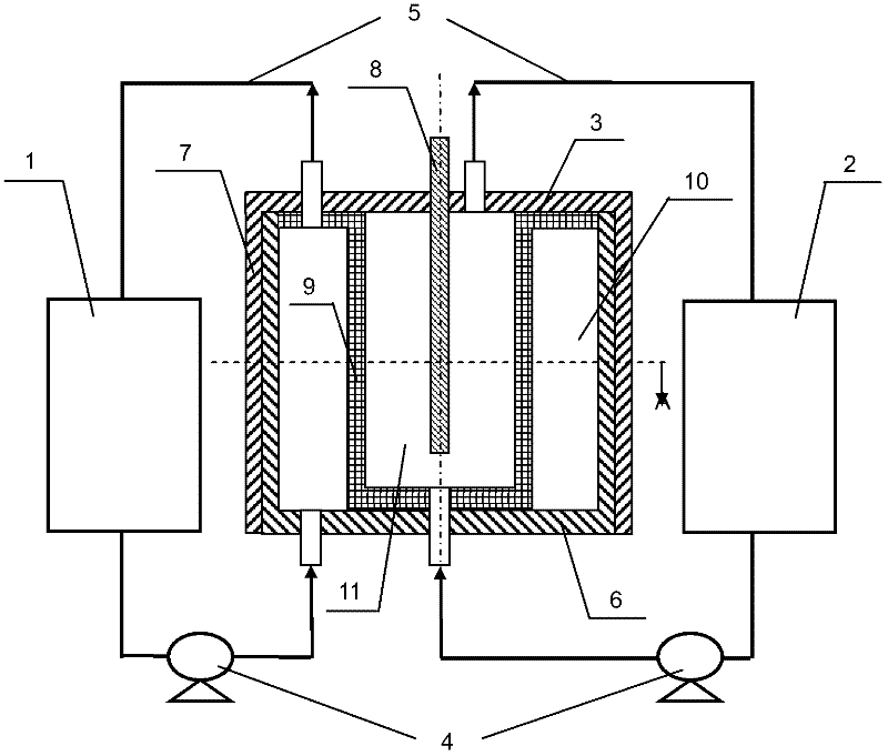
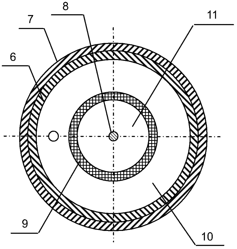
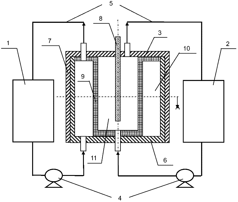
[0022] The lithium ion flow battery of the present invention is composed of a positive electrode suspension pool 1, a negative electrode suspension pool 2, a battery reactor 3, a liquid pump 4 and a sealed pipeline 5, such as figure 1 with figure 2 shown. Wherein, the positive electrode suspension pool 1 holds the mixture of the positive electrode composite material particles and the electrolyte solution, and the negative electrode suspension liquid pool 2 holds the mixture of the negative electrode composite material particles and the electrolyte solution. The mixture flows between the suspension tank and the battery reactor 3 through the sealed pipe 5 driven by the liquid pump 4 . The battery reactor 3 includes a positive electrode current collector 6 of a cylindrical structure, a plastic insulating case 7 placed on the outer layer of the cylindrical structure, a rod-shaped negative electrode current collector 8 placed inside the cylindrical structure, and a positive elect...


PUM

PropertyMeasurementUnit
pore sizeaaaaaaaaaa
pore sizeaaaaaaaaaa
porosityaaaaaaaaaa

Abstract

The invention provides a lithium ion flow redox battery, belonging to the technical field of lithium ion batteries. The lithium ion flow redox battery comprises a positive electrode suspension tank, a negative electrode suspension tank and a battery reactor, wherein the positive electrode suspension tank contains the mixture of positive electrode composite material particles and an electrolyte; the negative electrode suspension tank contains negative electrode composite material particles and an electrolyte; the battery reactor comprises a positive electrode current collector, a negative electrode current collector and one layer or a plurality of layers of microporous separators; the microporous separators separate the positive electrode current collector from the negative electrode current collector in an insulation mode so as to respectively form a positive electrode chamber and a negative electrode chamber; the positive electrode chamber is communicated with the positive electrode suspension tank through a seal pipeline; and the negative electrode chamber is communicated with the negative electrode suspension tank through a seal pipeline. Compared with a full vanadium flow redox battery, the lithium ion flow redox battery has the advantage of high energy density, the adoption of the environmentally-friendly and non-toxic electrolyte and low cost, and is applicable to large-scale energy storage of power grids.

Description

technical field [0001] The invention relates to a lithium-ion liquid flow battery that can be used for large-scale energy storage, and belongs to the technical field of lithium-ion batteries. Background technique [0002] The widespread use of electrical energy is considered one of the greatest achievements of mankind in the 20th century. The power industry has become one of the most important basic industries in the country. The modern power system is developing towards large power grids and large units, and maintaining the stability of the power grid is becoming more and more important for the power system. In order to achieve stable power supply, it is of great significance to develop efficient large-scale energy storage technology. [0003] The all-vanadium redox flow battery can realize the storage and release of electric energy through the change of the valence state of the active vanadium ions in the positive and negative electrode solutions. The positive and negat...

Claims


Application Information

Patent Timeline
Patent Type & Authority Applications(China)
IPC IPC(8): H01M8/18H01M4/38H01M4/48
CPCY02E60/528Y02E60/10Y02E60/50
Inventor 陈永翀王秋平张萍韩立
Owner BEIJING HAWAGA POWER STORAGE TECH
Learn More