

Antithrombogenic hollow fiber membranes and filters
A fiber membrane and filter technology, applied in blood filtration, membrane technology, suction devices, etc., can solve problems such as contraindications to patients
- Summary
- Abstract
- Description
- Claims
- Application Information
AI Technical Summary
Problems solved by technology
Method used
Image

Examples
Embodiment 1
[0217] Example 1. Diagram and calculation of packing area
[0218] Figure 20A is a scanning electron micrograph of a single hollow fiber. Figure 20A B is a schematic representation of a hollow fiber bundle. Figures 20A-20B and the calculations below highlight the ability of fiber bundles to provide surface area to resist coagulation when in contact with blood.
[0219] The calculations below are based on Figure 20B, which is a conceptual drawing of a commercially available CRRT blood filter composed of 5,000 fiber bundles with the following dimensions:
[0220] a) Diameter of encapsulation area + fiber area = 3.5 cm
[0221] b) The fiber has an outer diameter (OD) = 290 μm and an inner diameter (ID) = 200 μm
[0222] c) Total package and fiber area = πr 2 =3.142(3.5 / 2) 2 cm 2 =9.623cm 2
[0223] d) Area of the hollow part = π(ID / 2) 2 =3.142 / 4×(0.020) 2 cm 2 =3.142×10 -4 cm 2
[0224] e) The area of the hollow portion for 5,000 fibers = 5,000×3.142×10 -...
Embodiment 2
[0231] Example 2. Surface-modified macromolecules in thin films of PS / PVP polymer blends
[0232] Membranes were prepared to demonstrate that the hollow fiber membranes of the present invention may consist of surfaces in the mixture from which they are prepared. Surface-modified macromolecules (SMM, 5 wt%), polysulfone (PS, 10 wt%), and polyvinylpyrrolidone (PVP, 5 wt%) were dissolved in a mixture of dimethylacetamide and tetrahydrofuran (about 80 wt%). Films with a thickness of 254 μm were cast on Teflon substrates and subsequently dried and analyzed for surface fluorine and nitrogen content. Results are provided in Table 2 for the four solution-cast formulated films analyzed, each utilizing a different surface-modifying macromolecule.
[0233] Table 2
[0234]
[0235] For the four films, the surface fluorine content is provided by X-ray photoelectron spectroscopy (XPS) results, and the elemental analysis (EA) of the bulk (neat) SMM is provided for comparison. The diff...
Embodiment 3
[0236] Example 3. Surface-modified macromolecules in fibers of PS / PVP polymer blends
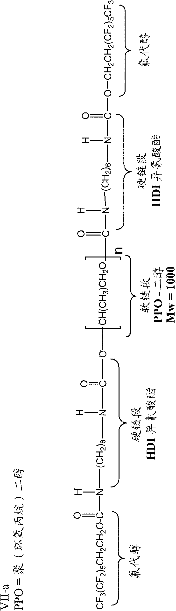
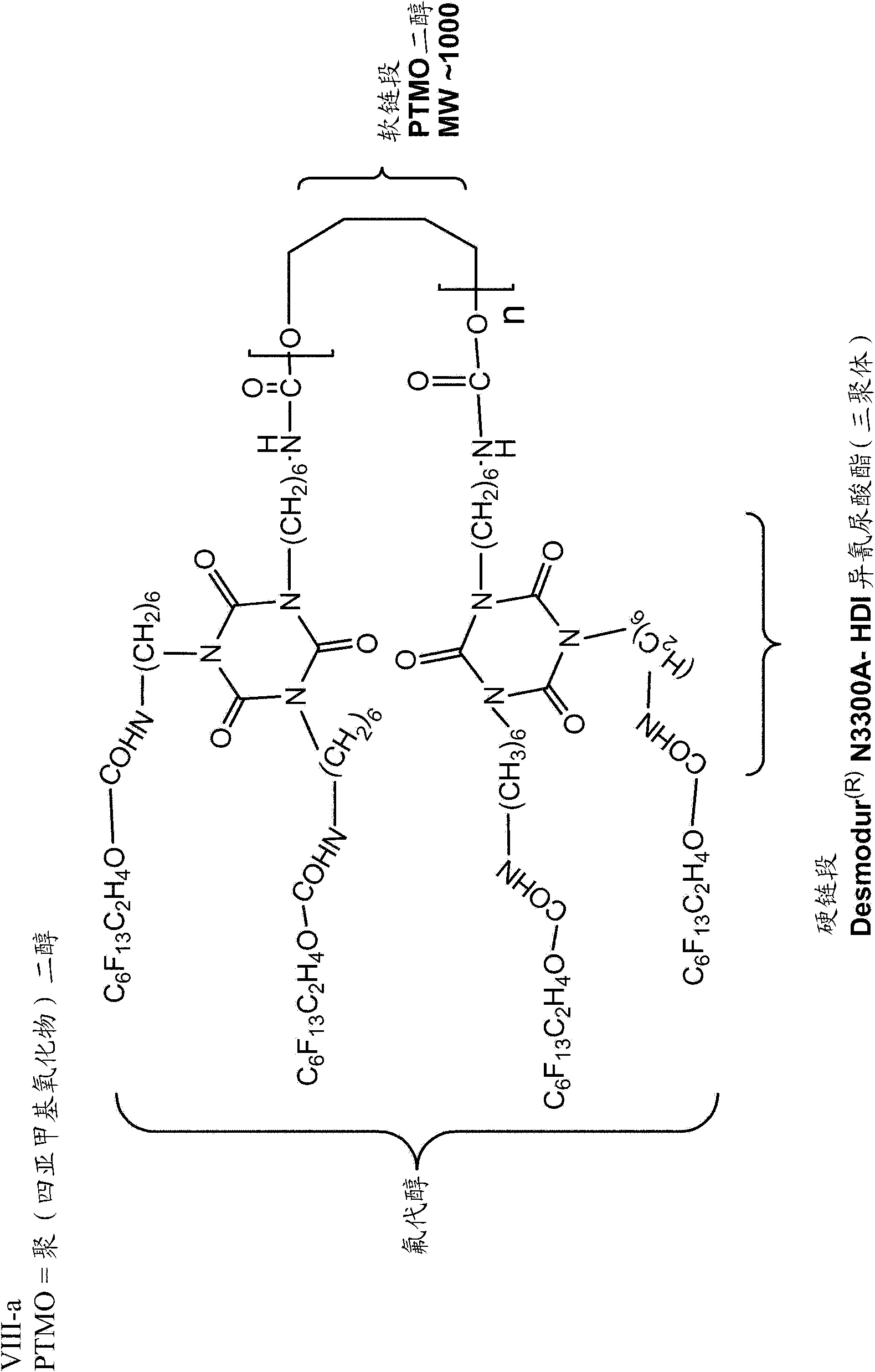
[0237] The fibers were also analyzed for fluorine and nitrogen content. The results are provided in Table 3 for the four solution spun fibers analyzed, each utilizing a different surface modifying macromolecule (VII-a, VIII-a, IX-a, and XI-a).
[0238] table 3
[0239]
[0240] X-ray photoelectron spectroscopy (XPS) data indicated that all SMM-modified fibers had varying degrees of surface fluorine in the inner (IS) and outer (OS) surfaces that actually come into contact with blood during hemodialysis.
[0241] Table 3 also provides the elemental analysis (EA) and %F of the SMM in the bulk, which indicates the amount of additive incorporated into the fiber compared to the amount targeted for incorporation. For VII-a, the EA of %F indicated that 6 wt% of the additive was incorporated, only 4 wt% was actually present. This loss of approximately 33% can be attributed to the harsh conditio...
PUM
| Property | Measurement | Unit |
|---|---|---|
| Outer diameter | aaaaa | aaaaa |
| The inside diameter of | aaaaa | aaaaa |
| Thickness | aaaaa | aaaaa |
Abstract
Description
Claims
Application Information