Vacuum ion plating method of wear-resisting layer on inner wall of metal cylinder

A technology of vacuum coating and metal cylinder, which is applied in the direction of ion implantation plating, vacuum evaporation plating, metal material coating process, etc., can solve the problems of uneven etching of tubular targets, easy demagnetization, and low utilization of targets. Achieve the effect of controllable concentration of ions, increased service life and good particle fineness

Active Publication Date: 2012-01-18
王敬达
View PDF5 Cites 17 Cited by
  • Summary
  • Abstract
  • Description
  • Claims
  • Application Information

AI Technical Summary

Problems solved by technology

However, the above method has many deficiencies: However, the existing multi-arc ion coating method produces thick multi-arc ion particles with fog drop phenomenon, the arc is concentrated on the magnetic ring, and the etching of the tubular target is uneven. The target surface must be corrected, and the distance between the magnet and the target needs to be adjusted in time. The low utilization of the target also greatly affects the working efficiency of vacuum plating; another disadvantage is that the ion beam of the multi-arc tubular target is dispersed, and the arc light is loose. Irregularity, serial movement on the surface of the target tube, uneven etching on the surface of the target tube, easy to produce grooves on the surface of both ends of the target tube, greatly affecting the service life of the target, this is because the arc is pulled by the outer motor to pull the target tube inside The magnetic steel moves back and forth, and the magnetic steel is easy to demagnetize under the high temperature condition in the tube, thus affecting the arc striking effect. The above shortcomings have a great impact on the quality and production efficiency of ion plating

Method used


Image

  • Vacuum ion plating method of wear-resisting layer on inner wall of metal cylinder
  • Vacuum ion plating method of wear-resisting layer on inner wall of metal cylinder
  • Vacuum ion plating method of wear-resisting layer on inner wall of metal cylinder

Examples


Embodiment Construction

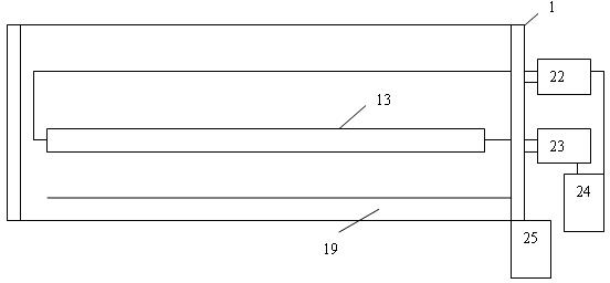
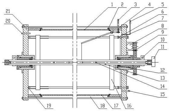
[0020] The two ends of the metal cylinder are provided with end caps which are insulated and sealed to isolate 2. The end cover can be made of metal, and the working room is formed in the metal cylinder, and the inner wall is plated. Top) Connect the vacuum exhaust port 15, vacuum gauge 5, temperature measuring hole 20 and mass flow meter 11, the electric heating tube collector 7, that is, the rotary commutator, connect the power supply to the electric heating tube 6, and provide power to the electric heating tube, in the center of the end cover Hollow target tube 13, the material of target tube can be set according to needs, as titanium tube etc., the hollow of target tube connects air hole 14, and the surface of target tube is provided with working gas outlet hole; Acetylene Gas - Used to coat various metals. A power supply for the auxiliary anode 19 is provided.

[0021] In order to coat the workpiece evenly, one method is to rotate or swing the auxiliary anode in the cyl...


PUM


Abstract

The invention provides a vacuum ion plating method of a wear-resisting layer on the inner wall of a metal cylinder. According to the invention, metal end caps with insulating, sealing and separating functions are arranged on two ends of the metal cylinder. A vacuum pumping pipe and a heating power supply input port are arranged on the end caps, such that temperature requirements of vacuuming and plating can be satisfied. An auxiliary anode applied with a biasing electrode is arranged in the cylinder. A hollow or solid column-shaped target material is positioned at the center of the cylinder. An arc welding power supply is applied on the target material. The metal cylinder is conducted to the other pole of the arc welding power supply. An auxiliary anode which can rotate or swing is arranged on the end cap of the metal cylinder. According to the invention, the cylinder is provided with a rotary sealing apparatus, and arc welding power supplies which operate independently are applied onboth ends of the target material. The structure provided by the invention can be manufactured into mobile and portable equipment used for plating pipes requiring bottom wear-resisting layers, and especially pipe walls of pipes with large calibers.

Description

technical field [0001] The invention relates to a plasma vacuum coating method and device for the inner wall of a metal cylinder. Background technique [0002] Plasma vacuum coating method has been relatively popular -------- using magnetron columnar arc source multi-arc ion coating, the device is to install a rotating magnetron columnar arc source (tubular) in the center of the coating chamber. It consists of a coating chamber, a workpiece turret, a magnetically controlled columnar arc source, an air inlet (different working gases need to be fed in when plating different materials) system, an arc source power supply, a workpiece heating source, an arc ignition system, a vacuum system, and a workpiece bias power supply composition. The column arc source is made of tubular metal material as the target material, and several bar-shaped permanent magnets are installed in the tube, and the permanent magnets move (including rotation and reciprocating motion) in the target tube. ...

Claims


Application Information

Patent Timeline
Patent Type & Authority Applications(China)
IPC IPC(8): C23C14/32
Inventor 王敬达
Owner 王敬达
Why Eureka
Try Eureka