Solar air-conditioner

A solar energy and air conditioning technology, applied in the field of solar air conditioning, can solve problems such as unfavorable energy saving, achieve excellent flexibility, solve technical problems, and ensure the effect of charging acceptability

Inactive Publication Date: 2012-01-18
芦福贵
View PDF7 Cites 6 Cited by
  • Summary
  • Abstract
  • Description
  • Claims
  • Application Information

AI Technical Summary

Problems solved by technology

[0002] Most of the air conditioners currently on the market are powered by mains electricity, which is not conducive to energy saving

Method used


Image

  • Solar air-conditioner
  • Solar air-conditioner
  • Solar air-conditioner

Examples


Embodiment 1

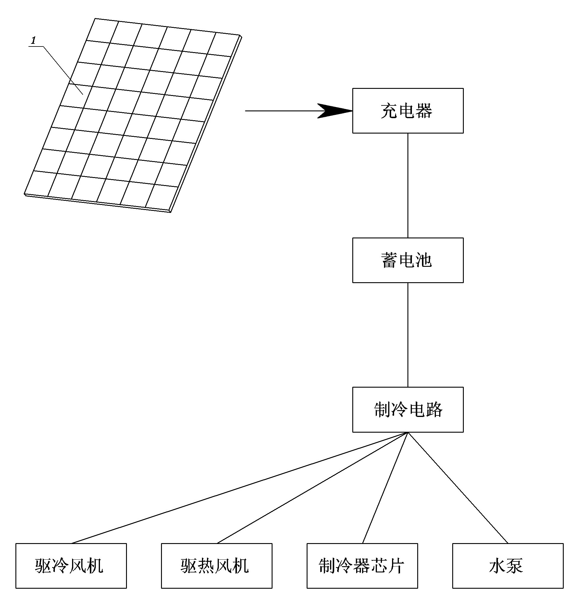
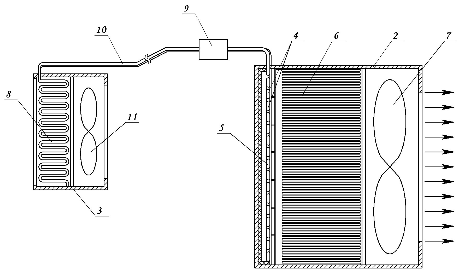
[0029] Embodiment one: see figure 1 , figure 2 with image 3, a solar air conditioner, a solar panel 1, a charger and a storage battery, a cold control circuit and a refrigerator, the refrigerant is composed of an indoor unit and an outdoor unit.

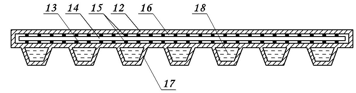
[0030] Described solar cell panel comprises at least one planar photothermal cell panel; This photovoltaic panel is surrounded by upper substrate 12 and lower substrate 13 to form a sealed chamber, and the upper and lower substrates in the sealed chamber are bonded by a plurality of bonding points 15 respectively. A photovoltaic cell 14 is connected and fixed, and a transparent resin 16 is filled in the sealed chamber.

[0031] The weight ratio composition of the positive electrode grid alloy material of the storage battery is: 0.22% Sn+0.01% Ag+0.02% Cu+0.02% A1+0.15% As, the remainder is Pb; the positive electrode active material composition adopts: Pb powder+1.295g / cm 3 h 2 S0 4 solution + 0.2% PTFE emulsion + 0.15% heter...

Embodiment 2

[0035] Embodiment 2: The content is basically the same as Embodiment 1, and the similarities will not be repeated. The difference is that the refrigeration control circuit includes a current mirror circuit arranged between the storage battery and the refrigerator, and a current mirror circuit connected to the current mirror circuit. A microcontroller and a clock circuit connected to the microcontroller, the current mirror circuit receives the electric energy of the storage battery and transmits it to the refrigerator, and the microcontroller controls the The magnitude of the current transmitted to the lamp body by the current mirror circuit.

[0036] The mirror circuit includes a resistor, a first transistor, a number of second transistors and a number of electrical switching elements, the collector of the first transistor is connected to the anode of the storage battery through the resistor, the emitter of the first transistor is grounded, and the collector The electrodes are...

Embodiment 3

[0037] Embodiment 3: The content is basically the same as Embodiment 1, and the similarities will not be repeated. The difference is: see image 3 , the lower base plate 13 is made of a material with strong thermal conductivity, and a cooling mechanism is arranged on the outer surface of the lower base plate. The grooves 17 are sequentially connected and filled with cooling liquid 18 , and each groove is connected to a liquid outlet and a liquid inlet respectively, and the liquid outlet and the liquid inlet are respectively communicated with a cooling pipeline.


PUM


Abstract

The invention discloses a solar air-conditioner, which comprises a solar power supply system and a refrigeration system, wherein the solar power supply system comprises a solar cell panel, a charger and a storage cell; the refrigeration system comprises a refrigeration control circuit and a refrigerator, wherein the refrigerator consists of an indoor unit and an outdoor unit; and the solar cell panel at least comprises a planer photo-thermal cell panel; the photo-thermal cell panel is a sealed chamber encircled by an upper baseplate and a lower baseplate, wherein photovoltaic cells are respectively adhered and fixed on the upper baseplate and the lower baseplate of the sealed chamber through a plurality of adhering points, and the sealed chamber is provided with transparent resin. According to the solar air-conditioner disclosed by the invention, electric energy obtained through solar energy conversion is used for refrigeration, therefore the energy sources can be saved, and the roof heat is reduced.

Description

technical field [0001] The invention relates to a new energy air conditioner technology, in particular to a solar air conditioner. Background technique [0002] Most of the air conditioners currently on the market are powered by mains electricity, which is not conducive to energy conservation. Air conditioners are mostly used in summer, which has a better amount of sunlight than other seasons. If the powerful solar energy is converted into cooling, it will produce huge economic and energy-saving effects. Contents of the invention [0003] The object of the present invention is to provide a solar air conditioner aiming at the problems existing in the prior art. [0004] The technical solution of the present invention is: a solar air conditioner, including a solar power supply system and a refrigeration system, the solar power supply system includes a solar panel, a charger and a storage battery, the refrigeration system includes a refrigeration control circuit and a refrig...

Claims


Application Information

Patent Timeline
Patent Type & Authority Applications(China)
IPC IPC(8): F24F5/00H02N6/00H02S30/10
CPCY02B10/24Y02B10/20Y02B10/10Y02E10/50Y02A30/272
Inventor 芦福贵
Owner 芦福贵
Why Eureka
Try Eureka