
Power transformer partial discharge detection system and method based on fiber bragg grating

A technology for partial discharge detection and power transformers, applied in the direction of testing dielectric strength, etc., can solve the problems of poor sensitivity of ultrasonic sensors, easy to be affected by electromagnetic interference, poor anti-interference ability, etc., to achieve strong anti-electronic interference ability and reduce the impact. , high precision effect

Inactive Publication Date: 2013-06-05
BEIHANG UNIV
View PDF4 Cites 0 Cited by
  • Summary
  • Abstract
  • Description
  • Claims
  • Application Information

AI Technical Summary

Problems solved by technology

[0004] The existing Chinese patent 200510000496.3 "Partial discharge measurement method and its device" directly measures the electrical pulse signal of partial discharge, which has problems such as poor anti-interference ability, low measurement frequency, narrow frequency band, and less information contained; Chinese patent CN201010023128.1 "On-line detection and positioning system for partial discharge in power transformers", 200920102761.2 "An ultrasonic planar array sensor suitable for detection of partial discharge in transformers" all use the ultrasonic detection method, the sensitivity of the ultrasonic sensor is poor, and it cannot be effectively detected on site signal; Chinese patent 200820152381.5 "Partial discharge detection system for gas-insulated composite electrical appliances" combines ultra-high frequency detection and acoustic emission detection technology, and the detection efficiency is high, but the acoustic emission sensor used is a traditional piezoelectric sensor, which is large in size and easy to detect. Affected by electromagnetic interference

Method used


Image

  • Power transformer partial discharge detection system and method based on fiber bragg grating

Examples


Embodiment Construction

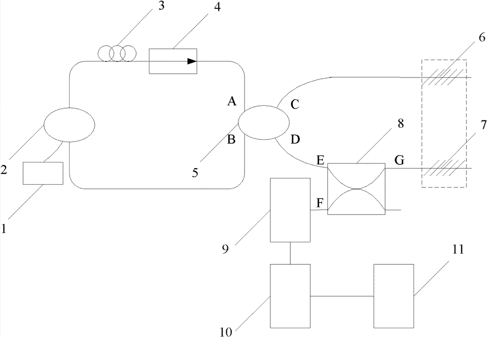
[0016] Such as figure 1 As shown, the partial discharge detection system for power transformers based on fiber Bragg gratings of the present invention includes: LD pump source 1, wavelength division multiplexer (WDM) 2, erbium-doped optical fiber (EDF) 3, isolator (ISO) 4. First and second fiber couplers 5 and 8, first and second fiber Bragg gratings (FBG) 6 and 7, photodetector 9, acoustic emission acquisition card 10, computer 11; wherein, LD pumping source 1 , WDM 2, EDF 3, ISO 4, and the first fiber coupler 5 are in the same loop to form a ring cavity erbium-doped fiber laser; the A port and B port of the first fiber coupler 5 are in the above loop; the first coupling The C port of the device 5 is connected to the first FBG 6, the D port of the first fiber coupler 5 is connected to the E port of the second fiber coupler 8; the G port of the second fiber coupler 8 is connected to the second FBG 7, and the second fiber The F port of the coupler 8 is connected with the photo...


PUM


Abstract

The invention discloses a power transformer partial discharge detection system based on a fiber bragg grating, which comprises an LD (Lead Detector) pumping source, a wavelength multiplexer, an erbium doped fiber, an isolator, a first fiber coupler, a second fiber coupler, a first fiber bragg grating, a second fiber bragg grating, a photoelectric detector, an acoustic emission collection card anda computer, wherein two input ends of the LD pumping source, the wavelength multiplexer, the erbium doped fiber and the first fiber coupler are in the same loop to form an annular cavity erbium dopedfiber laser; one output end of the first fiber coupler is connected with the first fiber bragg grating, the other output end of the first fiber bragg grating is connected with one input end of the second fiber coupler; one output end of the second fiber coupler is connected with the second fiber bragg grating, the other input end of the second fiber coupler is connected with the photoelectric detector; and the photoelectric detector is connected with the computer through the acoustic emission collection card. The power transformer partial discharge detection system is used for carrying out inservice real time and continuous monitoring on a transformer, and has the advantages of strong anti-electromagnetic interference capacity, small temperature influence, high detection precision and good flexibility.

Description

technical field [0001] The invention relates to a power transformer partial discharge detection system and detection method based on a fiber Bragg grating, and belongs to the technical field of acoustic emission nondestructive detection. Background technique [0002] Large-scale power transformer is one of the important equipment of power system and the core equipment of substation. Its operation status is directly related to the safe and economical operation of power system. With the development of the power system and the improvement of the voltage level, partial discharge (PD) has become one of the main reasons for the insulation degradation of power transformers, so the detection and evaluation of partial discharge has become an important means of transformer insulation status detection. . When a partial discharge occurs inside a power transformer in operation, the magnitude of the partial discharge reflects the condition of the insulation defect to a certain extent, th...

Claims


Application Information

Patent Timeline
Patent Type & Authority Patents(China)
IPC IPC(8): G01R31/12
Inventor 魏鹏刘奇孙志平李成贵屈玉福涂万里
Owner BEIHANG UNIV
Learn More