Integral condensing boiler

A condensing boiler, integrated technology, applied in fluid heaters, energy-saving heating/cooling, air heaters, etc., can solve the problems of poor film condensation heat transfer effect, tearing condensate film, poor condensation heat transfer conditions, etc. , to achieve the effects of reducing pollutant emissions, enhancing convective heat transfer, and compact structure

Active Publication Date: 2012-01-25
XI AN JIAOTONG UNIV
View PDF9 Cites 6 Cited by
  • Summary
  • Abstract
  • Description
  • Claims
  • Application Information

AI Technical Summary

Problems solved by technology

[0005] (1) The existing condensing boiler is a conventional boiler convection heat exchanger with a condensing heat exchanger installed at the end to form a separate condensing boiler structure, but the condensation heat transfer conditions of the conventional boiler flue gas are poor, and the increase in thermal efficiency is small
[0006] (2) The burner equipped with the existing separate condensing boiler still adopts the traditional atmospheric or diffuse combustion device, which has a high excess air coefficient and a low water dew point, which limits the latent heat recovery efficiency of water vapor condensation heat exchange; at the same time, the traditional combustion device Large amount of NOx emissions during combustion increases environmental pollution
[0007] (3) The existing integral condensing boiler systems mostly use hollow seamless or seamed steel pipes as convection and condensation heat transfer elements, and only convective heat transfer and water vapor condensation heat transfer occur on the wall contacting the flue gas and metal. The temperature of the flue gas in the center of the heating element is very high, and it is impossible to realize the overall convection and condensation heat transfer effect on the flue gas flow section, and there is no effective measure to tear the condensate film on the metal wall after the condensation heat transfer occurs, causing the film Condensation heat transfer effect is poor, and the thermal efficiency increase of condensing boiler is limited

Method used


Image

  • Integral condensing boiler
  • Integral condensing boiler
  • Integral condensing boiler

Examples


Embodiment Construction

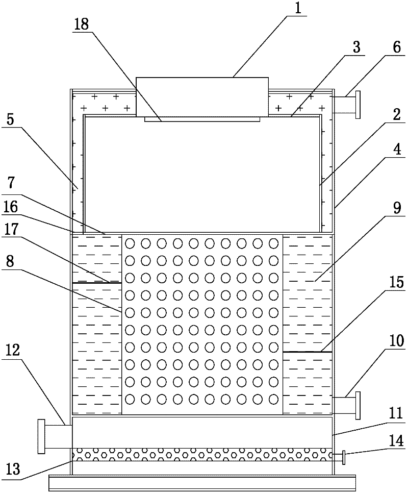
[0018] The present invention will be described in more detail below in conjunction with the accompanying drawings.

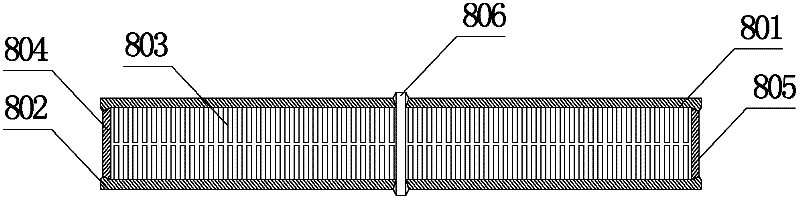
[0019] Such as figure 1 As shown, the integral condensing boiler includes a condensing boiler surrounded by an outer shell 4. Above the condensing boiler is a furnace 2, and a fully premixed flameless burner 1 is placed on the upper top plate 3 of the furnace 2. The furnace A water jacket 5 is covered between the outer wall of the shell 2 and the inner wall of the shell 4. The lower bottom plate 7 at the bottom of the furnace 2 is connected to the top of more than one plate-fin heat transfer element 8 for overall convection and condensation heat exchange. The bottom of the finned heat transfer element 8 is in communication with the top of the turning smoke chamber 11, and the condensate neutralization treatment device 13 with the condensate discharge pipe 14 is arranged under the turning smoke chamber 11, and the outer side of the turning smoke chamber 11 has T...


PUM


Abstract

The invention provides an integral condensing boiler. In the integral condensing boiler, a fully-premixed flameless burner fueled by oil gas fuels is used for radiant heat exchange in a boiler furnace, a platefin type heat transfer component is used for entire convection and condensation heat transfer and a flue gas mainstream temperature zone is directly inserted by welding a pin or a cast boss, thus effectively reducing the temperature gradient from the glue gas mainstream to a wall surface, continuously damaging a flowing boundary layer of the wall surface and a flue gas center and strengthening the heat convection; furthermore, condensation heat transfer can expand from the wall surface to the whole surface of the pin or the cast boss so that the condensation heat transfer area can be effectively enlarged; meanwhile, condensation heat transfer of water vapor in the flue gas can be strengthened, thus the whole convection and condensation heat transfer coefficients of the condensing boiler can be greatly improved; the condensation liquid can absorb partial harmful gases in the flue gas, such as CO2, NOx, SOx, and the like, thus pollutant emission can be effectively reduced. The boiler has a simple structure and high entire convection and condensation heat transfer coefficients and can be used for improving the conversion efficiency of thermal energy to the greatest extent.

Description

technical field [0001] The invention belongs to the technical field of thermal energy engineering, in particular to an integral condensing boiler. Background technique [0002] In recent years, in order to improve the atmospheric environment, my country has implemented coal-to-gas projects in large and medium-sized cities, making natural gas an increasing proportion of my country's energy consumption. In 2010, natural gas accounted for 5.3% of my country's energy consumption. In the next 20 years, the growth rate of natural gas demand will obviously exceed that of coal and oil. By 2020, it will increase to 10%, and the demand for natural gas will reach 203.7 billion m 3 , my country's energy is characterized by poor oil and little gas, and the reserves of oil and gas resources are seriously insufficient. In order to meet the growing demand, it is necessary to import a large amount of oil and natural gas. More importantly, oil and natural gas are clean energy. How to improve ...

Claims


Application Information

Patent Timeline
Patent Type & Authority Applications(China)
IPC IPC(8): F24H8/00
CPCY02B30/102Y02B30/00
Inventor 赵钦新苟远波姜薇薇王云刚
Owner XI AN JIAOTONG UNIV
Why Eureka
Try Eureka