Combustion settling chamber

A technology of combustion settling chamber and burner, which is applied in the field of separation, can solve the problems of unfavorable CO burnout, environmental and safety hazards, and the inability to quantitatively test the combustion degree of CO, so as to achieve the effect of complete combustion and protection of the outer wall of the shell

Inactive Publication Date: 2012-02-01
CISDI ENG CO LTD
View PDF6 Cites 3 Cited by
  • Summary
  • Abstract
  • Description
  • Claims
  • Application Information

AI Technical Summary

Problems solved by technology

Although the combustion settling chamber of this invention plays the role of dedusting, heat storage and promoting CO combustion to a certain extent on the electric furnace flue gas, the combustion settling chamber also has many dead angles, which is not conducive to CO burnout, and the combustion settling chamber cannot Quantitatively test the combustion degree of CO, which will cause potential danger to the environment and safety; the dust in the flue gas will slowly adhere to the ash discharge port, or even block the ash discharge port, which is not conducive to the ash discharge of the combustion settling chamber

Method used


Image

  • Combustion settling chamber
  • Combustion settling chamber
  • Combustion settling chamber

Examples


Embodiment 1

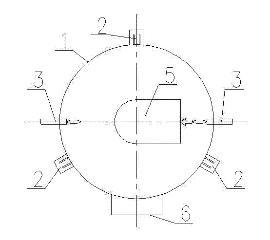
[0027] Such as figure 1 and figure 2 As shown, it is a schematic structural view of the first embodiment of the combustion settling chamber of the present invention. The combustion settling chamber of this embodiment includes a shell 1, a smoke inlet 5 and a smoke outlet 6 arranged on the shell 1, and a 1 bottom ash outlet 10. One or more than two burners 3 are provided on the inner wall of the housing 1. The number of burners 3 in this embodiment is set to two. When the dust-laden electric furnace flue gas enters the housing 1 Inside, under the action of gravity, the large-diameter dust particles fall to the ash outlet 10 at the bottom of the combustion settling chamber, and by setting the burner 3 on the inner wall of the shell 1, the CO and flue gas contained in the electric furnace flue gas can be removed The air mixed in the inlet 5 is exhausted through the flue gas outlet 6 after being fully combusted. A CO concentration detection device 9 is provided at the flue gas...

Embodiment 2

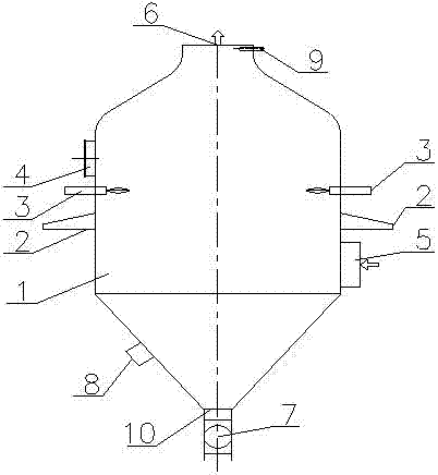
[0032] Such as image 3 and Figure 4 As shown, it is a schematic structural view of the second embodiment of the combustion and settling chamber of the present invention. The flue gas inlet 5 of the combustion and settling chamber of this embodiment is arranged on the side wall of the casing, and the flue gas outlet 6 is arranged on the top of the casing, and The flue gas inlet 5 is tangent to the housing 1. By setting the flue gas inlet 5 to be tangent to the housing 1, when the flue gas enters the interior of the housing 1 from the flue gas inlet 5, the flue gas will flow along the The inner wall of the spiral rises, which is more conducive to the deposition of dust. .

[0033] Other structures of this embodiment are the same as those of Embodiment 1, and will not be repeated here.


PUM


Abstract

The invention discloses a combustion settling chamber, which comprises a shell, a smoke inlet, a smoke outlet and an ash discharge hole, wherein the smoke inlet and the smoke outlet are arranged on the shell; the ash discharge hole is located at the bottom part of the shell; the inner wall of the shell is provided with at least combustor; and the position of the smoke outlet is provided with a carbon monoxide (CO) concentration detection device. Through arranging the combustors on the inner wall of the shell, CO contained in the smoke of an electric furnace is discharged through the smoke outlet after being fully burnt with air mixed into the smoke inlet; the CO concentration detection device arranged at the position of the smoke outlet is used for detecting the content of the CO in the discharged smoke; when the CO concentration is detected to exceed an allowed range, the amount of the air mixed into the smoke inlet is increased, and the CO contained in the smoke is fully burnt by utilizing the combustors so as to ensure the concentration of the CO of the outlet to be lower than allowed discharge concentration, thus, through full combustion and quantitative detection, the concentration of the CO contained in the smoke discharged from the combustion settling chamber disclosed by the invention meets an allowable value, thereby, potential harm cannot be caused to safety and environments any longer.

Description

Technical field [0001] The present invention is a separation technology field, which involves a kind of furnace flue gas burning depression room. Background technique [0002] A large amount of flue gas is generated during the steelmaking process, and the flue gas contains CO.In order to cool the flue gas generated during the cooling of the electric furnace, the flue gas generated by the electric furnace first entered the sedimentation room, removed the large particles of dust in the flue gas, and burned the CO part at the same time, and then cooled the flue gas to 300 ~After 400 ° C, mix with the air to cool down to 200 ° C and enter the dust removal system. [0003] In the past, some of the sedimentation rooms used to directly use the concrete structure, and there were also water -cooled tray structures, and the shape was mainly a square structure. This structure not only had more dead ends, COs could not be burned, and the dust settlement effect was poor, smoke gas, smoke gas....

Claims


Application Information

Patent Timeline
Patent Type & Authority Applications(China)
IPC IPC(8): F27D17/00F23G7/06
Inventor 董茂林李雨侯祥松孙明庆王毅
Owner CISDI ENG CO LTD
Why Eureka
Try Eureka