He-Ne laser tube with flat inner cavity and manufacturing method thereof

A helium-neon laser and flat technology, which is applied in the field of gas laser tube and its preparation, can solve the problems affecting the application and promotion of high-power flat discharge tube helium-neon laser, increasing the complexity and cost of the laser structure, and affecting the laser output power. Achieve the effect of reducing the cost of the whole machine, prolonging the life, and improving the output power of the laser

Inactive Publication Date: 2012-02-01
南京乐翔科技发展有限公司
View PDF5 Cites 3 Cited by
  • Summary
  • Abstract
  • Description
  • Claims
  • Application Information

AI Technical Summary

Problems solved by technology

[0006] However, this kind of external cavity or semi-external cavity structure increases the complexity and cost of the laser structure for the manufacturer. Although it is easy to adjust, it is very inconvenient for users who are not familiar with laser technology, and they often have to rely on the manufacturer for adjustment. and maintenance
Moreover, due to the insertion of the Brinell window in the cavity and the exposure of a certain optical path to the atmosphere, the loss in the cavity is increased, which affects the improvement of the laser output power.
In particular, the pollution of atmospheric dust to Brinell windows and concave spherical dielectric film mirrors will seriously affect the laser output power. Although various dust prevention measures (or ultra-clean environments) are taken, generally every 3 to 6 months Scrub the Brinell window and the concave spherical dielectric film mirror once (these problems do not exist for the inner cavity tube), these problems obviously greatly affect the application and promotion of this high-power flat discharge tube He-Ne laser

Method used


Image

  • He-Ne laser tube with flat inner cavity and manufacturing method thereof
  • He-Ne laser tube with flat inner cavity and manufacturing method thereof
  • He-Ne laser tube with flat inner cavity and manufacturing method thereof

Examples


Embodiment Construction

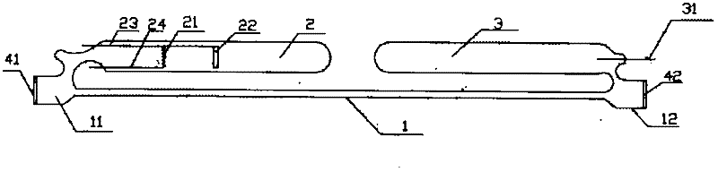
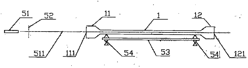
[0024] A flat helium-neon laser tube with an inner cavity of the present invention includes a flat discharge tube 1, a cathode bubble 2, and an anode bubble 3, and the cathode bubble 2 and the anode bubble 3 are respectively welded on the same side of the left and right ends of the flat discharge tube 1; The anode bubble 3 is provided with an anode 31, and the cathode bubble 2 is sealed with a long cathode side bar 23 and a short cathode side bar 24, and a connection is welded between the long cathode side bar 23 and the short cathode side bar 24. Both oxide cathode filaments 21; the two ends of the flat discharge tube 1 are respectively welded with a left mirror tube 11 and a right mirror tube 12, and on the end face of the left mirror tube 11 and the right mirror tube 12 Dielectric film reflectors are respectively arranged on the end surfaces, and the two dielectric film reflectors are respectively a planar dielectric film reflector 41 and a concave spherical dielectric film ...


PUM


Abstract

The invention discloses a He-Ne laser tube with a flat inner cavity. The He-Ne laser pipe comprises a flat discharge tube, mirrored tubes, dielectric film reflecting mirrors, a cathode bulb and an anode bulb, wherein an oxide cathode filament and a cathode lateral rod are arranged inside the cathode bulb, an anode is arranged in the anode bulb, the round mirrored tubes are respectively arranged at two ends of the flat discharge tube, and the dielectric film reflecting mirrors are respectively stuck to the two ends of each mirrored tube. The He-Ne laser tube disclosed by the invention has the advantages of high output laser power, convenience for user usage, long service life and the like. The perpendicularity of the reflecting mirrors serving as an optical cavity and a tube axis of the flat discharge tube is detected by adopting an He-Ne laser intra-cavity oscillation method, a spherical concave-surface reflecting mirror is rotated around the tube axis so as to make an intra-cavity oscillation mode filed in a long strip shape, the length-to-width ratio of the long strip shape is more than 3:1, and thus, the position of the spherical concave-surface reflecting mirror is determined.By utilizing the detecting method, the yield of manufacture is obviously increased.

Description

Technical field [0001] The invention involves a gas laser tube and its preparation method, especially the laser tube and its preparation method with a flat discharge section. Background technique [0002] The invention patent "high -power laser laser" (China Patent Number: 85100563) proposed the design and manufacturing laser pipe with a flat discharge tube, which can appropriately increase the horizontal cross section of the discharge pipe and significantly increase the laser output power of the laser, so as to obtain itLaser output high power.And seal the laser tube shell with soft glass through the low melting point.This patent is a typical outer cavity gas laser tube structure, that is, the laser tube is a gas container composed of discharge tube, two electrode bubbles, and two -cloth windows.Outside the tube, it is installed on the micro -regulatory rack to adjust their vertical with the laser tube axis, so that the optical resonance cavity resonance is resonated to obtain l...

Claims


Application Information

Patent Timeline
Patent Type & Authority Applications(China)
IPC IPC(8): H01S3/03H01S3/034H01S3/036
Inventor 王兆军凌一鸣
Owner 南京乐翔科技发展有限公司
Why Eureka
Try Eureka