
Catalyst For Purification Of Exhaust Gas

A technology for exhaust gas purification and catalyst, which is applied in physical/chemical process catalysts, catalyst activation/preparation, chemical elements of heterogeneous catalysts, etc. It can solve the problems of inability to obtain OSC and achieve the effect of excellent catalyst performance.

Inactive Publication Date: 2012-02-01
UMICORE SHOKUBAI JAPAN CO LTD +1
View PDF5 Cites 14 Cited by
  • Summary
  • Abstract
  • Description
  • Claims
  • Application Information

AI Technical Summary

Problems solved by technology

Also, the iron oxide content is preferably such that, as Fe 2 o 3 And in the range of 2 to 30% by weight, and when departing from this range, substantial OSC cannot be obtained
[0007] The OSC material containing cerium functions as a cocatalyst for the oxidation-reduction reaction, but in the techniques described in the above-mentioned Patent Document 1 and Patent Document 2, iron is present near the cerium in order to promote the catalytic performance of the cerium.

Method used


Image

  • Catalyst For Purification Of Exhaust Gas
  • Catalyst For Purification Of Exhaust Gas
  • Catalyst For Purification Of Exhaust Gas

Examples


preparation example Construction

[0074]

[0075] The catalyst of this aspect can be produced, for example, as follows. That is, after contacting the slurry of any one of the catalyst active components with the three-dimensional structure support, it is dried in air at a temperature of 50 to 300°C, preferably at a temperature of 80 to 200°C. 5 minutes to 10 hours, preferably drying for 5 minutes to 8 hours. Then, it is fired at a temperature of 300 to 1200°C, preferably at a temperature of 400 to 500°C, for 30 minutes to 10 hours, preferably for 1 hour to 5 hours. Next, a finished catalyst is obtained by allowing the slurry of any other catalytically active component to be supported in the same manner, and, if necessary, similarly allowing the slurry of any other catalytically active component to be supported.

[0076]

[0077] The catalyst of this embodiment is used for purification of exhaust gas of internal combustion engines, especially gasoline engines. The space velocity (S.V.) at this time is 10,0...

Embodiment 1

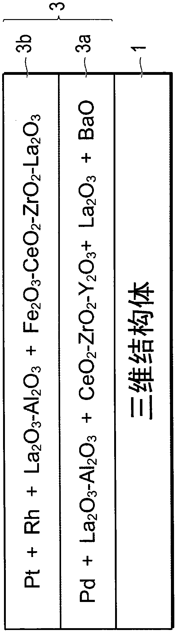
[0084] In order to form the lower catalyst layer, first, palladium nitrate as a palladium raw material, alumina containing 3% by weight of lanthanum oxide, barium hydroxide as a barium oxide raw material, and CeO 2 -ZrO 2 -Y 2 o 3 Composite oxides (CeO 2 : ZrO 2 : Y 2 o 3 = 10:80:10 (mass ratio)) each raw material is weighed so that after firing it satisfies Pd:La 2 o 3 :BaO:La 2 o 3 -Al 2 o 3 : CeO 2 -ZrO 2 -Y 2 o 3 =0.4:2:2:80:50 (mass ratio). Then, the weighed raw materials were mixed and stirred for one hour, and then wet pulverized to obtain a slurry I.

[0085] In addition, in order to form the upper catalyst layer, platinum nitrate as a platinum raw material, rhodium nitrate as a rhodium raw material, alumina containing lanthanum at 3% by weight, and Fe 2 o 3 -CeO 2 -ZrO 2 -La 2 o 3 Composite oxides (Fe 2 o 3 : CeO 2 : ZrO 2 : La 2 o 3 =0.1:30:59.9:10 (mass ratio)) Each raw material is weighed so that after firing it satisfies Pt:Rh:La 2 o ...

Embodiment 2

[0088] Fe to be used in slurry II 2 o 3 -CeO 2 -ZrO 2 -La 2 o 3 The ratio of each component of the composite oxide is Fe 2 o 3 : CeO 2 : ZrO 2 : La 2 o 3 = 0.3:30:59.7:10 (mass ratio), and the same method as in Example 1 was used to prepare catalyst C.


PUM

PropertyMeasurementUnit
specific surface areaaaaaaaaaaa
particle sizeaaaaaaaaaa

Abstract

PROBLEM The present invention is directed to provide a catalyst for purifying exhaust gas capable of maintaining a superior catalytic performance even when the catalyst is exposed to an exhaust gas at a high temperature of 800 DEG C. or higher. SOLUTION The catalyst for purifying exhaust gas of the present invention comprises a catalytically active component containing a noble metal and a promoter containing an oxygen storage material both being supported on a carrier. The oxygen storage material comprises cerium, zirconium, and iron, and content of iron in the oxygen storage material is 0.01% by mass or more and less than 0.70% by mass (Fe2O3 conversion) relative to the total mass of the oxygen storage material. And the oxygen storage material is (a) a complex oxide or a solid solution of iron and a metal comprising cerium and zirconium; or (b) an iron is supported on a complex oxide or a solid solution of a metal comprising cerium and zirconium.

Description

technical field [0001] The invention relates to a catalyst for exhaust gas purification. In particular, the present invention relates to an exhaust gas-purifying catalyst capable of maintaining excellent catalyst performance even when exposed to high-temperature exhaust gas. Background technique [0002] In recent years, a large number of technologies related to exhaust gas purification have been proposed, and in particular, many proposals have been made regarding technologies for treating exhaust gas generated by internal combustion engines such as gasoline engines, diesel engines, and engines using biofuels or fuels containing methanol. [0003] As a catalyst for purifying exhaust gas generated by an internal combustion engine, a catalyst capable of simultaneously removing nitrogen oxides (hereinafter, also referred to as "NO x "), carbon monoxide (hereinafter, also referred to as "CO"), and hydrocarbons (hereinafter, also referred to as "HC"), or in an oxygen-excess stat...

Claims


Application Information

Patent Timeline
Patent Type & Authority Applications(China)
IPC IPC(8): B01J23/89B01D53/94F01N3/10
CPCF01N3/101B01J23/83B01J37/0244B01D2255/2063B01D2255/407B01D2255/908B01J2523/00Y02T10/22B01J23/002B01D2255/1021B01J23/894B01D2255/2042F01N2370/02B01D2255/2065B01D2255/9022B01D2255/20715B01D2255/1023B01D53/945B01D2255/2061B01D2255/1025F01N3/0864B01D2255/20738Y02T10/12B01J2523/3706B01J2523/3712B01J2523/48B01J2523/842B01J23/89F01N3/10B01J23/00
Inventor 三木田光修池上高广池田正宪后藤秀树
Owner UMICORE SHOKUBAI JAPAN CO LTD
Learn More