
Coaxial double-telecentric imaging optics system

A technology of imaging optics and imaging systems, applied in optics, optical components, microlithography exposure equipment, etc., can solve the problems of increasing design cost and difficulty of installation and calibration, increasing system cost and difficulty of installation and calibration, and high requirements for eliminating stray light and assembly , to achieve high lighting uniformity, reduce the difficulty of realization, and reduce the difficulty of installation and calibration

Active Publication Date: 2012-02-08
SHANGHAI MICRO ELECTRONICS EQUIP (GRP) CO LTD
View PDF5 Cites 18 Cited by
  • Summary
  • Abstract
  • Description
  • Claims
  • Application Information

AI Technical Summary

Problems solved by technology

[0004] In U.S. Patent No. 5,689,602, a coaxial illumination optical system structure is proposed. The advantage of this structure is that the illumination light path structure is simple and the energy utilization rate is high. The disadvantage is that the illumination field of view of this structure cannot be controlled, and it is easy to enter into the imaging system. Stray light, the corresponding mechanical structure stray light elimination requirements and assembly requirements will be relatively high
[0005] In U.S. Patent No. 5,715,050, a coaxial illumination double-telecentric optical measurement system is proposed. The advantage of this system is that the position error of the object image plane has a low impact on the measurement accuracy, but the magnification of the system is low, and the size of the illumination area cannot be controlled. Therefore, high measurement accuracy cannot be obtained; and it also needs an additional optical system behind the bi-telecentric imaging system to ensure a good contrast image, which increases the design cost and the difficulty of installation and calibration
[0006] In the US patent US6639653B2, a bi-telecentric objective lens optical structure is proposed. When this structure is applied to a system with a small field of view and a high magnification, the structure will appear too complicated, which will increase the system cost and the difficulty of installation and calibration.

Method used


Image

  • Coaxial double-telecentric imaging optics system
  • Coaxial double-telecentric imaging optics system
  • Coaxial double-telecentric imaging optics system

Examples


Embodiment 1

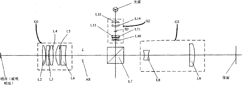
[0050] Such as figure 1 As shown, a coaxial double-telecentric imaging optical system in this embodiment includes a coaxial lighting system, an imaging system, and a light blocking element. The coaxial lighting system includes a light source, an lighting The objective lens group G2, the beam splitting element L7 and the front group objective lens group G1 uniformly illuminate the object surface. In this embodiment, the light blocking element is an aperture stop AS, located between the beam splitting element L7 and the front objective lens group G1, shared by the coaxial illumination system and the imaging system. The light source can be a halogen lamp, LED, or an optical fiber that conducts light energy of a halogen lamp or LED. The illumination light source used in this embodiment is a near-infrared light source with an effective wavelength of 1000nm to 1300nm. The illumination objective lens group G2 includes a plano-convex lens L15, a biconcave lens L14, an aperture stop ...

Embodiment 2

[0063] Figure 4 Shown is a schematic structural view of the coaxial double-telecentric imaging optical system of Embodiment 2 of the optical system of the present invention. Such as Figure 4 As shown, the imaging optical system provided by this embodiment includes a coaxial illumination system, an imaging system and a light blocking element. The coaxial illumination system includes an illumination objective lens group G2 sequentially along the optical axis from the light source to the object plane direction, divided into The beam element L7, the front group objective lens group G1 and the right-angle internal reflection prism L1 uniformly illuminate the object surface. The light blocking element includes an aperture stop AS2 and an aperture stop AS1, the aperture stop AS2 is arranged between the illumination objective lens group G2 and the beam splitting element L7, and the aperture stop AS1 is arranged between the beam splitting element L7 and the rear objective lens group...

Embodiment 3

[0071] Figure 5Shown is a schematic structural view of the coaxial double-telecentric imaging optical system of Embodiment 3 of the optical system of the present invention. Such as Figure 5 As shown, the difference between Embodiment 3 and Embodiment 2 is that there is no right-angle internal reflection prism L1, and other structures and structural parameters in Embodiment 3 are the same as Embodiment 2, and the above purpose and effect can be achieved.


PUM


Abstract

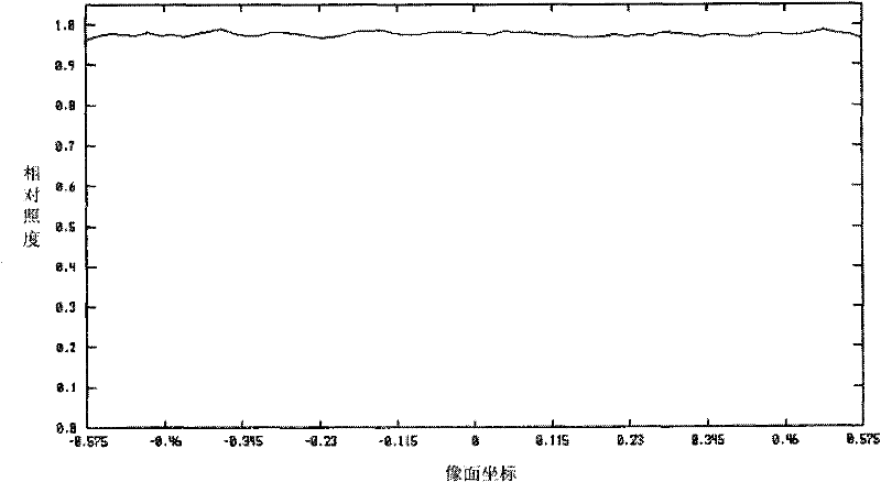
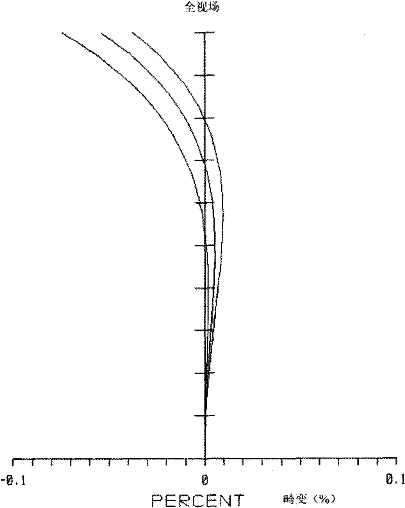
The invention discloses a coaxial double-telecentric imaging optics system, which comprises a coaxial illumination system, an imaging system and a light blocking element, wherein a front objective lens group and a beam splitting element are shared by the coaxial illumination system and the imaging system; a light source, an illumination objective lens group, the beam splitting element and the front objective lens group form the coaxial illumination system; the coaxial illumination system and the light blocking element form a Kohler illumination system to provide illumination with good evenness for an object plane; and the front objective lens group, the beam splitting element, a rear objective lens group and the light blocking element form a double-telecentric imaging system with small distortion and high multiplying power. According to the coaxial double-telecentric imaging optics system, high illumination evenness can be obtained, an imaged image has a good contrast ratio, and the measurement precision of the whole system is finally improved. Meanwhile, the coaxial double-telecentric imaging optics system has a simple structure, and system cost and realization difficulty are reduced.

Description

technical field [0001] The invention relates to the technical field of semiconductors, in particular to a coaxial double-telecentric imaging optical system in semiconductor lithography equipment. Background technique [0002] In semiconductor packaging lithography equipment and flat panel display lithography, the position alignment device is one of the very important devices. Structurally speaking, the position alignment device can be divided into on-axis position alignment device and off-axis position alignment device Two categories. The use of off-axis position alignment devices can reduce the requirements for the design, processing and assembly of optical projection systems. The alignment method is often implemented by measurement methods based on machine vision technology. The imaging lens is one of the core components of the machine vision system. The quality of its optical performance will directly determine the accuracy of the final alignment measurement. [0003] G...

Claims


Application Information

Patent Timeline
IPC IPC(8): G02B13/22G03F7/20
Inventor 杨晓青徐兵蔡巍陈跃飞
Owner SHANGHAI MICRO ELECTRONICS EQUIP (GRP) CO LTD
Learn More