Test method and device for monitoring steel wire fretting fatigue state

A technology of fretting fatigue and test method, which is applied in the direction of testing wear resistance and using stable tension/pressure to test the strength of materials, etc. It can solve the problems that the failure mechanism of steel wire fretting fatigue cannot be studied, and achieves wide practicability and effect Good, simple structure effect

Inactive Publication Date: 2012-02-15
CHINA UNIV OF MINING & TECH
View PDF9 Cites 25 Cited by
  • Summary
  • Abstract
  • Description
  • Claims
  • Application Information

AI Technical Summary

Problems solved by technology

[0003] At present, the test methods and devices used for fretting fatigue include: Patent No. 200810304928.3 discloses an axial fatigue test method and device for applying superimposed wear loads to large-diameter shaft test pieces. The cause of fatigue fracture and life prediction of specimens under wear load and fatigue load are helpful, but this experimental device is suitable for shaft specimens; a steel wire fretting fatigue testing machine disclosed in patent numbers 200910182122.6 and 200920233073.X can only examine The influence of different fretting fatigue parameters on the fretting fatigue life of steel wire cannot study the fretting fatigue failure mechanism of steel wire. During the experiment, the contact load between steel wires changes due to fretting wear; th...

Method used


Image

  • Test method and device for monitoring steel wire fretting fatigue state
  • Test method and device for monitoring steel wire fretting fatigue state
  • Test method and device for monitoring steel wire fretting fatigue state

Examples


Embodiment Construction

[0016] An embodiment of the present invention will be further described below in conjunction with accompanying drawing:

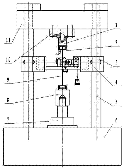
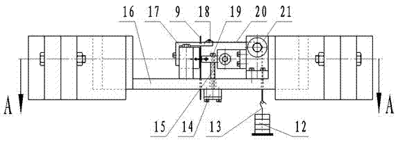
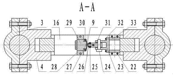
[0017] The test method for monitoring the fretting fatigue state of the steel wire of the present invention: first, one end of the test steel wire 9 is fixed on the upper clamping block 1, and the concave horizontal support 16 is adjusted so that the test steel wire 9 vertically passes through the L-shaped connecting frame 17 respectively. and the round hole of the concave horizontal support 16, the lower end of the test steel wire 9 is fixed on the lower clamping block 8, and then the hydraulic lifting platform 7 is started by the computer-controlled electro-hydraulic servo hydraulic system to stretch the test steel wire 9 downward, so that the test The steel wire 9 is gradually straightened, and when the tensile force borne by the test steel wire 9 reaches the set initial load, the operation of the hydraulic lifting platform 7 is stopped. Adjust the conca...


PUM


Abstract

The invention discloses a test method and a device for monitoring a steel wire fretting fatigue state. The device comprises a base, a support column, a top beam, a hydraulic lifting platform and a horizontal loading device. The test method comprises the following steps that two ends of a tested steel wire passing through the horizontal loading device are fixed respectively; the tested steel wire is stretched until the tested steel wire bears a preset initial load; the horizontal loading device is moved so that loading steel wires in the horizontal loading device compress tightly the tested steel wire; the hydraulic lifting platform is controlled to move up and down to apply alternate loads to the tested steel wire; the tested steel wire generates fretting fatigue; a tangential force is transmitted to a spoke-type pull-press sensor through an internal thread connecting rod arranged on a loading block, wherein an acoustic emission sensor is arranged on an upper grip block of the top beam; and the test is stopped when the tested steel wire is broken because of fretting fatigue. The device can dynamically record a tangential force between contact steel wires and tested steel wire acoustic emission signals in an experimental process, and provides an effective basis for research on a steel wire fretting zone, crack generation and fracture mechanisms of a fretting zone, and influences of the crack generation and the fracture mechanisms on a fretting fatigue life. The device has a simple structure, is convenient for operation and has good effects.

Description

technical field [0001] The invention relates to a test method and a device, in particular to a test method and a device suitable for dynamically monitoring the fretting fatigue state of a steel wire. Background technique [0002] Steel wire rope has good bending flexibility and load-bearing capacity, so it is widely used as traction cable for transportation machinery, hoisting cable for mining machinery, support cable for passenger cableway, load-bearing steel cable for cable-stayed bridge, etc. The bearing strength and service life of steel wire rope Longevity is very important to the safe operation of these application equipment. During the operation of these equipment, the steel wire rope is subject to repeated stretching and bending and dynamic loads, so that the internal strands of the steel wire rope and the steel wires in the strands are subject to fretting wear of different fretting amplitudes, and they must also withstand alternating stress. Smaller fretting ampli...

Claims


Application Information

Patent Timeline
IPC IPC(8): G01N3/08G01N3/56
Inventor 王大刚张德坤张泽锋
Owner CHINA UNIV OF MINING & TECH
Why Eureka
Try Eureka