Molding mold for glass fiber reinforced plastic grate
A forming mold and FRP technology, which is applied in the field of FRP grid forming molds, can solve the problems of high energy consumption and achieve energy saving, precise temperature control and high production efficiency
- Summary
- Abstract
- Description
- Claims
- Application Information
AI Technical Summary
Problems solved by technology
Method used
Image

Examples
Embodiment 1
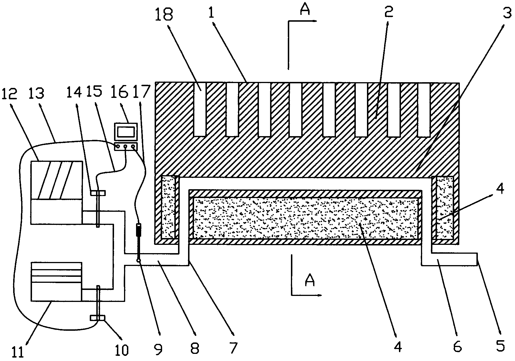
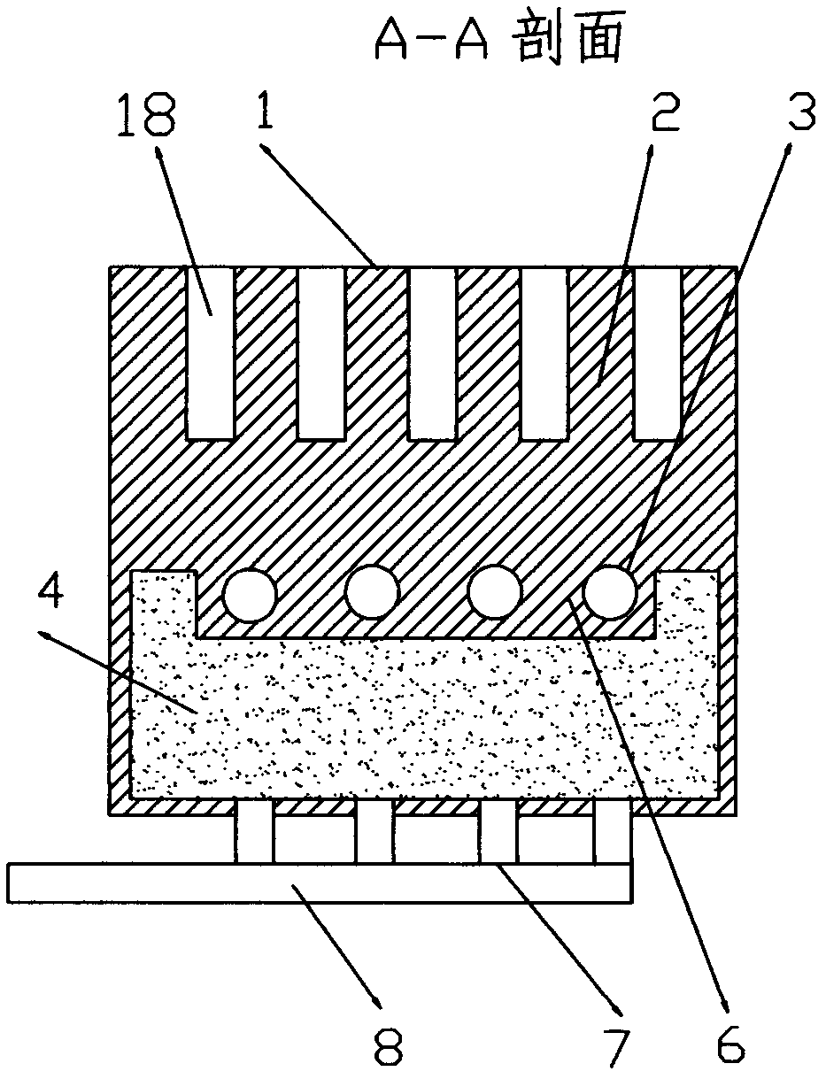
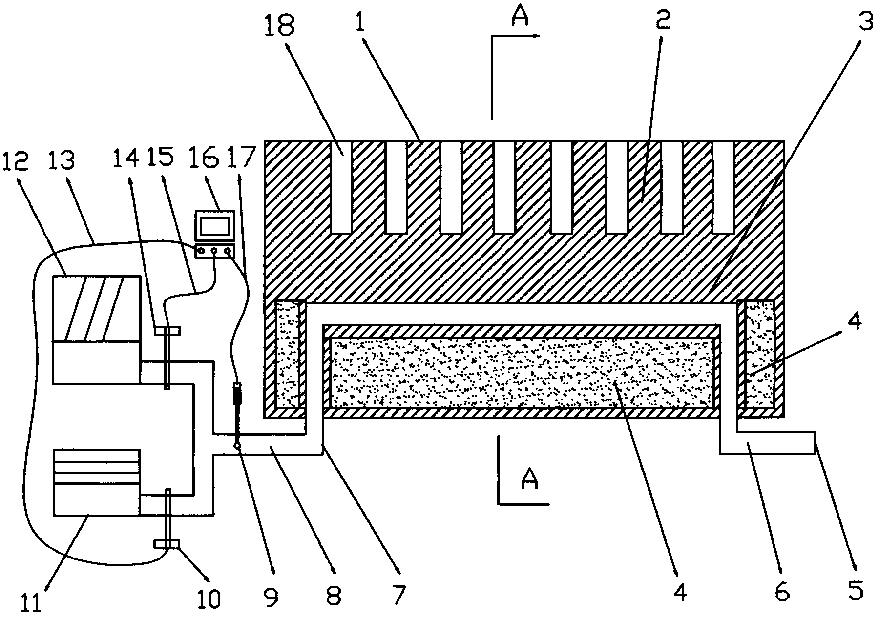
[0023] like figure 2 The FRP grating forming mold shown includes a forming template 2 placed under the FRP grating, several heating pipes 6 placed under the forming template 2, and the forming template 2 is a steel plate with a thickness of 100mm. The temperature control chamber 3 is an empty chamber at the bottom of the forming template 2, the forming template 2 and the temperature control chamber 3 are connected as a whole, and the height of the temperature control chamber 3 is 60 mm; the heating pipe 6 and the insulation layer 4 In the temperature control chamber 3, several heating pipes 6 are close to the upper top surface of the temperature control chamber (3), and the heat preservation layer 4 is wrapped on the left and right sides and the lower side of the temperature control pipe 6, and the heat preservation layer 4 is the resistance Made of combustible plastic or non-combustible mineral wool; the respective outlets 5 and inlets 7 of several heating pipes 6 are connec...
Embodiment 2
[0025] like figure 2 As shown, the FRP grating forming mold includes a forming template 2 placed under the FRP grating, several heating pipes 6 placed under the forming template 2, and the forming template 2 is a steel plate with a thickness of 120mm. The temperature control chamber 3 is an empty chamber surrounded by the forming template 2 and the steel plate below; the forming template 2 and the temperature control chamber 3 are connected as a whole, and the height of the temperature control chamber 3 is 80mm. The heating pipe 6 and the insulation layer 4 are in the temperature control chamber 3, several heating pipes 6 are close to the lower surface of the molding template 2, and the insulation layer 4 is wrapped around the left and right sides and the lower side of the heating pipe 6. The insulation layer 4 material is polyurethane foam. The outlets 5 and inlets 7 of several heating pipes 6 are connected below the temperature control chamber 3, and several inlets 7 are c...
Embodiment 3
[0029] as attached figure 1 And attached figure 2 As shown, the FRP grating forming mold includes a forming template 2 placed under the FRP grating, several heating pipes 6 placed under the forming template 2, and the forming template 2 is a steel plate with a thickness of 150 mm. The height of the temperature control chamber 3 is 100 mm. The heating pipeline 6 and the insulation layer 4 are in the temperature control chamber 3, and several heating pipelines 6 are close to the upper top surface of the temperature control chamber (3), and the insulation layer 4 is wrapped around the left and right sides of the heating pipeline 6 and On the lower side, the insulation layer 4 is made of non-combustible rock wool. The respective outlets 5 and inlets 7 of several heating pipes 6 are connected below the temperature control chamber 3 , and several inlets 7 are connected to the same main pipe 8 on which a temperature measuring instrument 9 is connected.
[0030] The heat source de...
PUM
| Property | Measurement | Unit |
|---|---|---|
| thickness | aaaaa | aaaaa |
| height | aaaaa | aaaaa |
Abstract
Description
Claims
Application Information
 - R&D
- Intellectual Property
- Life Sciences
- Materials
- Tech Scout
- Unparalleled Data Quality
- Higher Quality Content
- 60% Fewer Hallucinations
Browse by: Latest US Patents, China's latest patents, Technical Efficacy Thesaurus, Application Domain, Technology Topic, Popular Technical Reports.
© 2025 PatSnap. All rights reserved.Legal|Privacy policy|Modern Slavery Act Transparency Statement|Sitemap|About US| Contact US: help@patsnap.com