
System for treating dye wastewater and method for treating triphenylmethane dye wastewater

A technology for triphenylmethane and dye wastewater, which is applied in chemical instruments and methods, oxidized water/sewage treatment, water/sludge/sewage treatment, etc., can solve problems such as high cost and large energy consumption, and achieve fast reaction speed. , Increase the reaction rate constant, and improve the effect of substandard effluent

Active Publication Date: 2012-02-22
HARBIN INST OF TECH
View PDF6 Cites 8 Cited by
  • Summary
  • Abstract
  • Description
  • Claims
  • Application Information

AI Technical Summary

Problems solved by technology

[0003] The present invention aims to solve the technical problem of large energy consumption and high cost in the existing method of treating dye industrial wastewater by chemical advanced oxidation, and provides a system for treating dye wastewater and a method for treating triphenylmethane dye wastewater

Method used


Image

  • System for treating dye wastewater and method for treating triphenylmethane dye wastewater
  • System for treating dye wastewater and method for treating triphenylmethane dye wastewater
  • System for treating dye wastewater and method for treating triphenylmethane dye wastewater

Examples


specific Embodiment approach 1

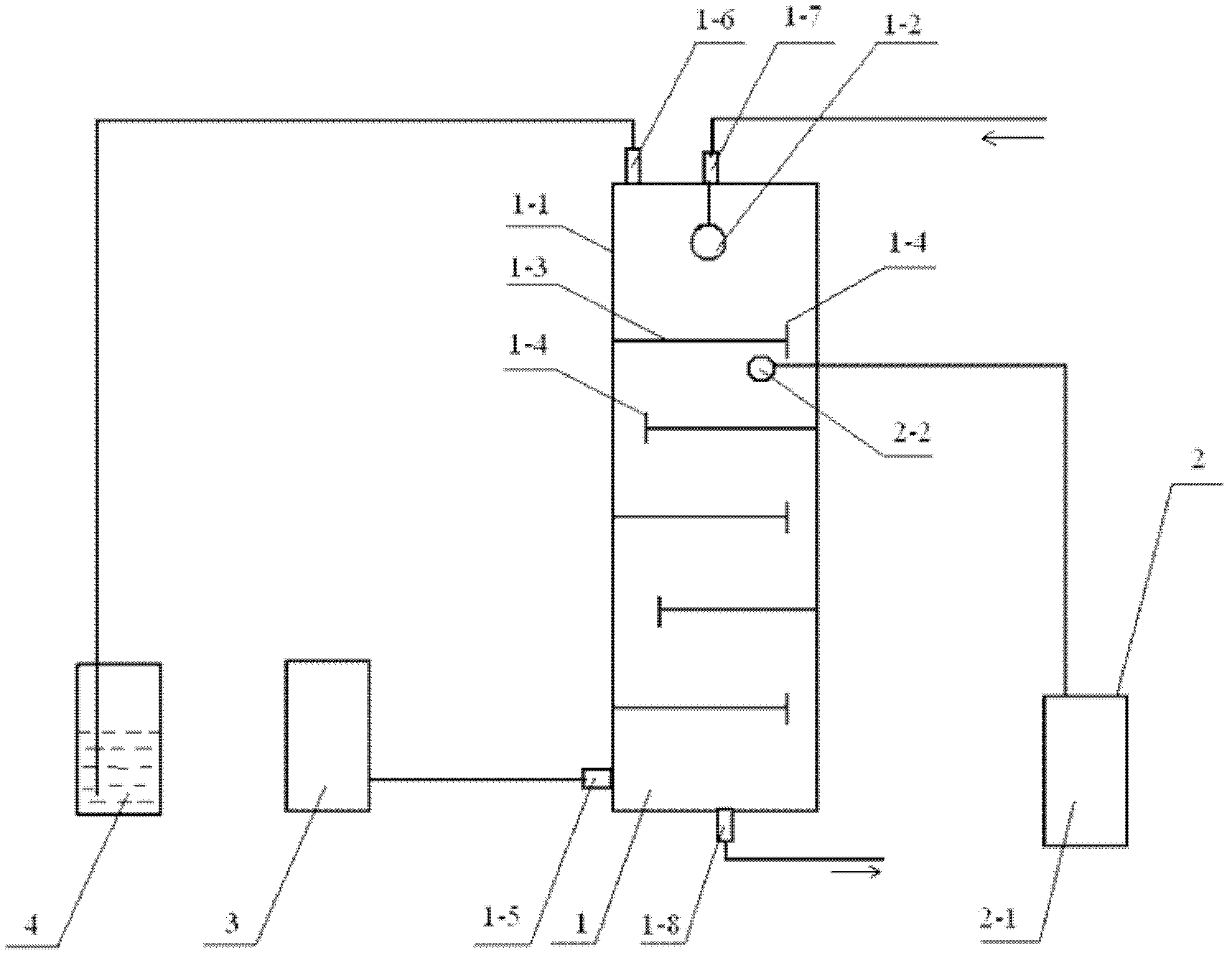
[0011] Specific implementation mode one: (please refer to the attached figure 1 ) A system for treating dye wastewater in this embodiment is composed of a sieve plate tower 1, an ultrasonic system 2, an ozone generator 3 and an ozone tail gas treatment device 4; -2, composed of sieve plate 1-3, overflow weir 1-4, air inlet 1-5, air outlet 1-6, water inlet 1-7 and water outlet 1-8, the diameter and height of sieve plate tower 1 The ratio is 1:5-10, the number of sieve plates 1-3 is 5-10, the water inlet 1-7 is connected with the water inlet distributor 1-2; the ultrasonic system 2 is composed of an ultrasonic generator 2-1 and a The ultrasonic probe 2-2 connected by the ultrasonic generating device 2-1 is composed of; The air inlets 1-5 are connected, and the gas outlets 1-6 of the sieve plate tower 1 are connected with the ozone tail gas treatment device 4 .

[0012] A system for treating dye wastewater in this embodiment utilizes a sieve tray tower combined with ultrasound ...

specific Embodiment approach 2

[0013] Embodiment 2: This embodiment differs from Embodiment 1 in that the ratio of the diameter to the height of the sieve tray column 1 is 1:6-8. Others are the same as in the first embodiment.

specific Embodiment approach 3

[0014] Embodiment 3: The difference between this embodiment and Embodiment 1 or 2 is that the number of sieve trays 1-3 of the sieve tray column 1 is 6-8. Others are the same as in the first or second embodiment.


PUM

PropertyMeasurementUnit
Concentrationaaaaaaaaaa

Abstract

The invention provides a system for treating dye wastewater and a method for treating triphenylmethane dye wastewater separately and relates to a device for treating dye wastewater and a method for treating dye wastewater. The system and the method can be used for solving the technical problem that by adopting the existing chemical advanced oxidation method for treating dye industrial wastewater,the energy consumption is large and the cost is high. The system consists of a sieve-plate tower, an ultrasound system, an ozone generator and an ozone tail gas treatment device; and an ultrasonic probe is arranged under the first sieve plate of a sieve-plate tower top meter, the ozone generator is communicated with the gas inlet of the sieve-plate tower, and the gas outlet of the sieve-plate tower is communicated with an ozone tail gas treatment device. The method comprises the following steps: adding triphenylmethane dye wastewater into the sieve-plate tower through a water inlet, simultaneously starting an ultrasonic generating device and the ozone generator, circulating the water flowing from the water outlet of the sieve-plate tower once, and finishing the treatment of wastewater after 4-6 cycles. The device and method provided by the invention have the advantages of low energy consumption and high treatment speed, and can be used in the field of wastewater treatment.

Description

technical field [0001] The invention belongs to equipment for dye wastewater and a method for treating dye wastewater. Background technique [0002] my country is the world's largest producer of dyes. The annual discharge of dye industry wastewater has reached 157 million tons. Moreover, artificial dye wastewater is developing in the direction of anti-oxidation and anti-photolysis, so the current dye industry wastewater is mostly high-chroma, highly toxic, and refractory organic wastewater. The existing method of treating dye industrial wastewater by chemical advanced oxidation method is to carry out by adding electric energy, catalyst and oxidizing agent, as the Chinese patent with publication number CN 1609010A discloses "a kind of dye wastewater treatment method", adopts ultrasonic and ozone Integrated process for the treatment of azo dye wastewater. The source of ozone generation is oxygen, which is provided by gas cylinders, and the operation safety is poor; the powe...

Claims


Application Information

Patent Timeline
IPC IPC(8): C02F1/36C02F1/78C02F101/32
Inventor 任南琪周显娇郭婉茜丁杰
Owner HARBIN INST OF TECH
Learn More