
Crank shaft type electromagnetic switching mechanism

A technology for electromagnetic switches and crankshafts, applied in the direction of non-polar relays, etc., can solve the problems of low maintenance power, large swinging gap of moving contacts, low noise, etc., and achieve easy guarantee of pressure and spacing, small swinging gap, and small contact wear. Effect

Inactive Publication Date: 2013-01-09
湖南科立电力建设有限公司 +1
View PDF3 Cites 0 Cited by
  • Summary
  • Abstract
  • Description
  • Claims
  • Application Information

AI Technical Summary

Problems solved by technology

[0002] For a long time, hundreds of millions of transmission lines and electrical equipment have used electromagnetic switches to open and close. There are about several types of electromagnetic switch mechanisms: (1) The traditional electromagnet switch mechanism maintains high power and noise during operation. , the coil and the iron core are prone to overheating during frequent operations. There are certain requirements, the structure is complex, the cost is high, and the electromagnetic compatibility is poor; (3) There is no current in the closing coil when the shrapnel hanging buckle electromagnetic switch mechanism is working, but the opening circuit relay also consumes power. The opening circuit structure and wiring (4) The motor closing mechanism is large in size and high in cost, and the starting current of the motor is large when closing, and the voltage-loss opening electromagnetic mechanism is complicated, and the voltage-loss coil also needs to rely on electric power to maintain; (5) Spring energy storage electromagnetic switch The mechanism is large in size, complex in structure, high in cost, and cannot realize multiple reclosing control; (6) The combination of electromagnetic switch power saver and traditional electromagnet switch mechanism can reduce energy consumption to a certain extent, but the cost of power saver is high , complex wiring, rarely used in engineering
Therefore, the electromagnetic switch mechanisms currently used at home and abroad cannot fundamentally solve the problems of size, cost, energy consumption, noise, reliability and practicality at the same time. This is a big problem that needs to be solved urgently.

Method used


Image

  • Crank shaft type electromagnetic switching mechanism
  • Crank shaft type electromagnetic switching mechanism
  • Crank shaft type electromagnetic switching mechanism

Examples


Embodiment

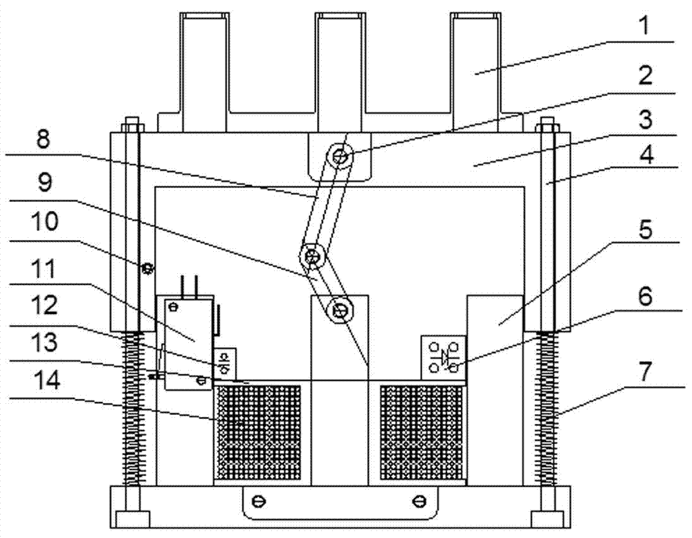
[0020] See figure 1 — Picture 10 :

[0021] The invention consists of a movable contact bracket 1, a positioning rod 2, a movable iron core 3, a guide rod 4, an iron core 5, a rectifier bridge 6, a spring 7, a connecting rod 8, a crankshaft 9, a touch rod 10, a travel switch 11, and a capacitor 12. , The skeleton 13 and the coil 14, wherein the coil 14 is wound in the skeleton 13, the rectifier bridge 6, the capacitor 12 are installed on the skeleton 13, the skeleton 13 is installed in the middle of the iron core 5, and the two lead wires of the coil 14 are connected to the rectifier bridge 6. On the DC output end, there are two guide rods 4 and two springs 7, the two guide rods 4 are respectively installed on the bases on both sides of the iron core 5, and the two springs 7 are respectively sleeved in the guide rods 4. The touch rod 10 is installed on one side of the moving iron core 3, the travel switch 11 is installed on one side of the iron core 5, the positioning rod 2, th...


PUM


Abstract

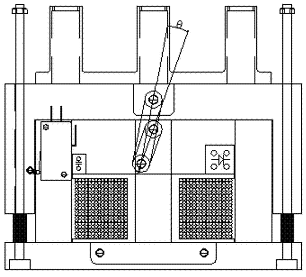
The invention relates to a crank shaft type electromagnetic switching mechanism, comprising a moving contact bracket, a movable iron core, an iron core, a rectifier bridge, a spring, a capacitor, a framework and a coil, wherein the moving contact bracket is mounted on the movable iron core; the coil is wound in the framework; the rectifier bridge and the capacitor are mounted on the framework; the framework is mounted in the middle of the iron core; two lead-out wires of the coil are connected with a direct-current output end of the rectifier bridge; a positioning rod is mounted on the movingiron core; the positioning rod is connected with one end of a connecting rod; the upper middle part of the iron core is connected with one end of a crank shaft; the other end of the crank shaft is connected with the other end of the connecting rod; and an included angle between a center line of shaft holes at both ends of the connecting rod and a center line of two shaft holes of the crank shaft is determined by adjusting a radius of the crank shaft or a center distance of the shaft holes at both ends of the connecting rod. The crank shaft type electromagnetic switching mechanism provided by the invention has the advantages of simple structure, small volume, low cost, high reliability, small maintenance current after switching on and no noise in use.

Description

Technical field [0001] The invention relates to an electromagnetic switch mechanism, which is mainly used for circuit breakers and contactors in high and low voltage electrical equipment. Background technique [0002] For a long time, hundreds of millions of transmission lines and electrical equipment have used electromagnetic switches for opening and closing. The electromagnetic switch mechanisms are as follows: (1) The traditional electromagnet switch mechanism maintains high power and noise during operation. , The coil and the iron core are easy to overheat during frequent operation. When closing, the moving contact has a large swing gap and the main contact is worn; (2) The permanent magnet electromagnetic switch mechanism maintains low power and low noise when it is working, but it is not There are certain requirements, complex structure, high cost, and poor electromagnetic compatibility; (3) There is no current in the closing coil when the shrapnel hanging electromagnetic s...

Claims


Application Information

Patent Timeline
Patent Type & Authority Patents(China)
IPC IPC(8): H01H51/04
Inventor 盛集
Owner 湖南科立电力建设有限公司
Learn More