Three-dimensional elliptical vibration cutting device

A technology of elliptical vibration and cutting devices, which is applied in the direction of driving devices, turning equipment, manufacturing tools, etc., can solve the problems of difficult tool holder design, difficult to obtain high-order modes, difficult system modeling and control, etc., and achieve simple and reliable preloading methods , achieve precise tracking control, simplify modeling and control effects

Active Publication Date: 2012-03-14
HUAWEI TEHCHNOLOGIES CO LTD
View PDF7 Cites 54 Cited by
  • Summary
  • Abstract
  • Description
  • Claims
  • Application Information

AI Technical Summary

Problems solved by technology

The problems of this device are: ①. The design of the tool holder is difficult, and it is difficult to obtain the required high-order mode; ②. The frequency of the three-dimensional elliptical vibration cutting motion and other elliptical motion parameters depend on the nonlinear structural dynamic parameters of the tool holder, which is difficult to obtain. Independent control, lack of flexibility; ③. With open-loop control, it is impossible to obtain undistorted three-dimensional elliptical vibration cutting motion
The problem with this device is: ①. The method of preloading three piezoelectric stacks with preload bolts along the diagonal direction of the piezoelectric stack may result in uneven preload obtained by each piezoelectric stack; ②.Due to sharing the same pre-tightening bolt, when the piezoelectric stack drives the tool to move along their respective axes, there are kinematic coupling and force coupling in the system, which makes it difficult to model and control the system

Method used


Image

  • Three-dimensional elliptical vibration cutting device
  • Three-dimensional elliptical vibration cutting device
  • Three-dimensional elliptical vibration cutting device

Examples


Embodiment Construction

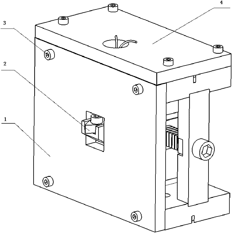
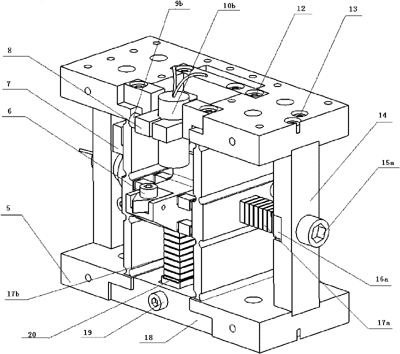
[0039] The front baffle 1 is fixedly connected with the base 5 through screws 3, the upper baffle 4 is fixedly connected with the base, the diamond tool 2 is fixedly connected with the tool holder on the base through set screws 16, and the X-direction support beam 14 is fixedly connected with set screws 2 13 is fixedly connected to the right side of the substrate, the fixed end of the X-direction piezoelectric stack 17a is fixedly connected to the X-direction piezoelectric stack seat 16a, and the X-direction piezoelectric stack seat 16a is connected to the X-direction support beam 14 through the X-direction pre-tightening bolt 15a Fixed connection, the X-direction stainless steel spherical body 11a is fixedly connected to the free end of the X-direction piezoelectric stack 17a, and the front end of the X-direction stainless steel spherical body 12a is connected to the X-direction right guide arm 511;

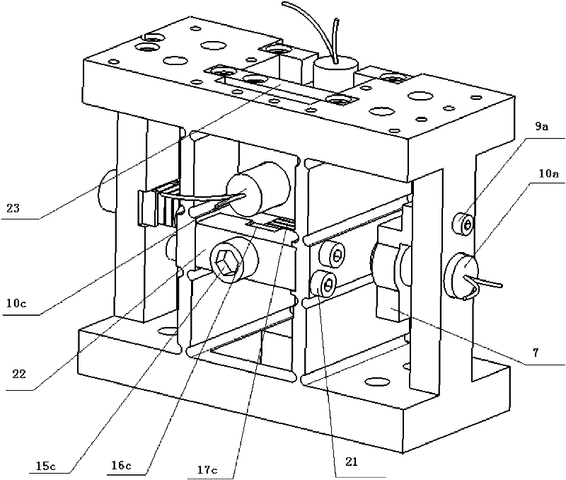
[0040] The fixed end of the Y-direction piezoelectric stack 17b is connected...


PUM


Abstract

The invention relates to a three-dimensional elliptical vibration cutting device, belonging to the field of cutting and ultra-precision cutting machining of materials which are difficult to machine. A diamond cutter is guided through flexible hinge mechanisms respectively along an X direction, a Y direction and a Z direction, and further, is driven by three piezoelectric stacks respectively alongthe X direction, the Y direction and the Z direction; the piezoelectric stacks of the X direction and the Z direction are preloaded by preloading screw bolts along respective axial direction; the piezoelectric stack of the Y direction is preloaded through a screw bolt screwing wedge; the preloading processes of the three directions are mutually independent; through regulating and matching the initial phase position and the amplitude of a driving signal for each of the three piezoelectric stacks, the projections of the cutter location point movements of the diamond cutter in an X-Y plane and aY-Z plane are elliptical motions, and the projection of the cutter location point movements of the diamond cutter in an X-Z plane is reciprocating elliptical motion or linear motion. The three-dimensional elliptical vibration cutting device has a novel and simple structure, is easy to implement, and is beneficial to obtaining the best cutting machinability of the diamond cutter.

Description

technical field [0001] The invention belongs to the field of cutting and ultra-precision cutting of difficult-to-machine materials, and in particular relates to a three-dimensional elliptical vibration cutting device. Background technique [0002] Diamond tools have many incomparable advantages, but the types of workpiece materials that can be cut are very limited. For ferrous materials such as hardened steel, and hard and brittle materials such as silicon carbide, severe diamond tool wear will be caused during the cutting process, which will deteriorate the machined surface quality and reduce the machining accuracy. In order to expand the range of diamond-cuttable materials, some improved cutting methods have been proposed, such as cryogenic cutting, carbon saturation cutting and elliptical vibration cutting. The research so far shows that three-dimensional elliptical vibration cutting is the most promising cutting method, which has many advantages such as suppressing tool...

Claims


Application Information

Patent Timeline
Patent Type & Authority Applications(China)
IPC IPC(8): B23B1/00B23Q5/02B23Q17/22
CPCB23B29/125B23B27/20B23B2260/108B23B2260/146B23B2265/16
Inventor 周晓勤刘培会林洁琼王刚朱志伟
Owner HUAWEI TEHCHNOLOGIES CO LTD
Why Eureka
Try Eureka