Optimizing control method for sintering waste heat power generation system

A technology of optimized control and waste heat power generation, applied in the steam generation method using heat carrier, electrical program control, furnace control device, etc., can solve the problems of unstable sintering thermal system, difficulty in recycling, low quality of waste heat, etc.

Active Publication Date: 2012-03-21
SINOSTEEL ANSHAN RES INST OF THERMO ENERGY CO LTD
View PDF5 Cites 22 Cited by
  • Summary
  • Abstract
  • Description
  • Claims
  • Application Information

AI Technical Summary

Problems solved by technology

[0006] 1) The exhaust gas flow rate of the sintering cooler is very large, but the low-temperature section (below 150°C) and part of the mid-temperature section exhaust gas have no use value, while the average temperature of the high-temperature section and the usable part of the mid-temperature section exhaust gas is between 300 and 380°C. Due to the influence of the ore dropping temperature of the sintering machine and the air leakage rate of the cooler, the quality of waste heat is not high, and it is difficult to recycle
[0007] 2) In addition, the power generation system has high requirements on the quality of waste heat steam. Due to the instability of the sintering thermal system, the fluctuating range of waste gas temperature is above ±100°C, causing the temperature fluctuation of waste heat steam to exceed the standard, forcing the waste heat power station to shut down frequently, which seriously threatens the safety of steam turbines. Security, Stability and Longevity

Method used


Image

  • Optimizing control method for sintering waste heat power generation system
  • Optimizing control method for sintering waste heat power generation system
  • Optimizing control method for sintering waste heat power generation system

Examples


Embodiment Construction

[0068] The specific implementation manners of the present invention will be further described in detail below in conjunction with the accompanying drawings.

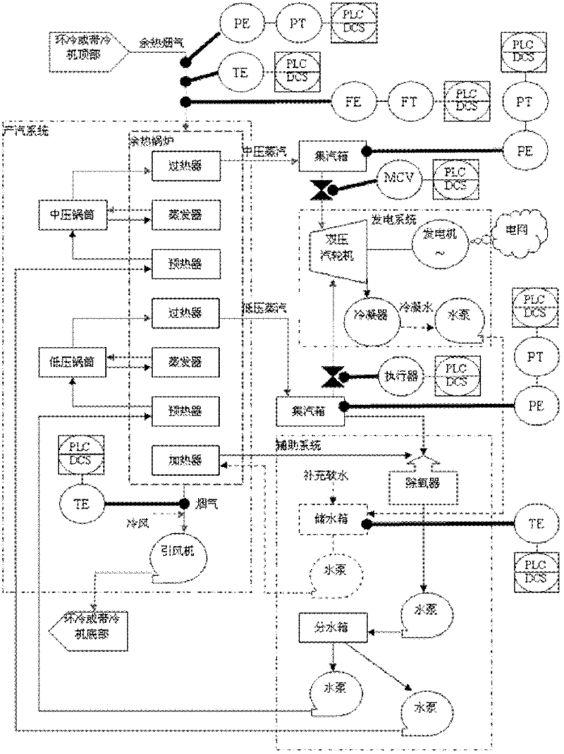
[0069] See figure 1 , a block diagram of the optimal control principle of a sintering waste heat power generation system in the present invention, including a waste heat boiler and a dual-pressure steam turbine. A medium-pressure steam collection box and a low-pressure steam collection box are arranged between the waste heat boiler and the double-pressure steam turbine. The medium-pressure steam collection box and the A medium-pressure regulating valve and a medium-pressure pressure sensor are provided between the dual-pressure steam turbines, and a low-pressure regulating valve and a low-pressure pressure sensor are provided between the low-pressure steam collecting tank and the dual-pressure steam turbine;

[0070] A flue gas flowmeter, a flue gas thermometer and a flue gas pressure detection device are installed at th...


PUM


Abstract

The invention relates to an optimizing control method for a sintering waste heat power generation system; the optimizing control method is characterized in that when parameters of a waste heat boiler and a steam turbine and the smoke flow and the inlet / outlet temperature of the waste heat boiler are constant, the power generation capacity of the steam turbine is only related to the pressure of middle pressure steam and low pressure steam which are output by the waste heat boiler, and the power generation capacity of the steam turbine is maximized by controlling the pressure of middle pressure steam and low pressure steam which are output by the waste heat boiler. Compared with the prior art, the optimizing control method has the beneficial effects: (1). the optimum control on a waste heat recycling system can be realized; and when external conditions change, the real-time automatic tracking is carried out and the optimal pressure value is adjusted; (2). the optimizing control method not only can be used for carrying out optimum control on the sintering waste heat power generation system put into operation, but also can be used for checking the design of the sintering waste heat power generation system and optimizing the design, thereby obtaining parameters such as the optimal outlet temperature of a preheater of the waste heat boiler, the optimal temperature of an evaporator, the optimal outlet temperature of a superheater, the optimal flow of the middle pressure steam and the low pressure steam, and the like and selecting the appropriate steam turbine.

Description

technical field [0001] The invention relates to the field of sintering waste heat recovery in iron and steel enterprises, in particular to an optimal control method for a sintering waste heat power generation system. Background technique [0002] At present, the energy consumption of the sintering process accounts for about 9% to 12% of the total energy consumption of iron and steel enterprises, and the waste heat discharged by it accounts for about 50% of the total energy consumption of sintering. During the cooling process of sinter, the heat taken away by the cooler air accounts for about 30% of the total energy consumption of sintering. Recycling this part of heat energy (circular cooling or cooling air discharge with cooler) has a great effect on energy saving and consumption reduction in the sintering process. pivotal role. In addition, heat energy accounting for 20% of the total energy consumption of sintering is discharged by the main exhaust fan. [0003] The main...

Claims


Application Information

Patent Timeline
Patent Type & Authority Applications(China)
IPC IPC(8): G05B19/418F27D19/00F27D17/00F22B1/18F01K27/02F01K11/02
CPCY02P10/25
Inventor 任铁良王春凯方会斌陈巍林金柱梁伯平林建军陈深灿乐晓芳江荣才李志红李宝东蒋卫杨懿李鹏元李岩
Owner SINOSTEEL ANSHAN RES INST OF THERMO ENERGY CO LTD
Why Eureka
Try Eureka