Control system of chain type current transformer

A technology of chain-type converters and control systems, applied in the direction of converting AC power input into DC power output, output power conversion devices, electrical components, etc., can solve the problems of low reliability and low scalability, and achieve reliability High, conducive to the expansion of the effect

Active Publication Date: 2012-04-04
BEIJING SIFANG JIBAO AUTOMATION +1
View PDF4 Cites 27 Cited by
  • Summary
  • Abstract
  • Description
  • Claims
  • Application Information

AI Technical Summary

Problems solved by technology

Such a centralized control system often cannot meet the requirements and has low scalability and low reliability.

Method used


Image

  • Control system of chain type current transformer
  • Control system of chain type current transformer
  • Control system of chain type current transformer

Examples


Embodiment Construction

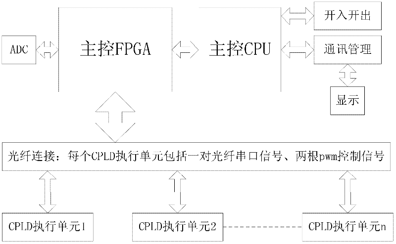
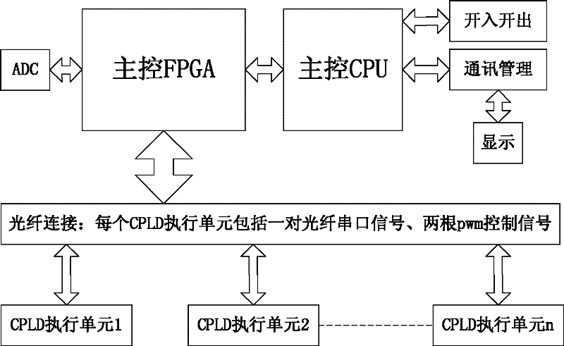
[0020] figure 1 It is the electrical schematic diagram of the control system of the chain-link converter of the present invention, and the control system of the chain-link converter includes a central processing unit CPU, a programmable logic device array FPGA, a complex and programmable A programmable logic device CPLD; the programmable logic device array FPGA controls the ADC conversion module to perform voltage and current analog sampling of the input and output of the chain converter, and the complex programmable logic device CPLD and the programmable logic device array FPGA adopt 4. Interconnect with the optical fiber, including a pair of optical fiber serial ports to send and receive signals and two optical fiber PWM control signals to connect to each other. The programmable logic device array FPGA is connected to the central processing unit CPU through a data bus, and the CPU can download control commands to FPGA, the FPGA sends ADC sampling data and the DC voltage and ...


PUM


Abstract

This invention discloses a control system for realizing a chain type current transformer; the system disclosed by this invention uses a distributed control method so as to satisfy a multi-chain-link expandable control demand in the chain type current transformer; a FPGA (Field Programmable Gate Array) utilizes a parallel processing function, abundant I / O (Input / Output) pins and an expandable internal logic unit so as to realize the operational processing for a plenty of data and the chain type expansion control of the current transformer; a CPU (Central Processing Unit) utilizes own abundant internal resources so as to realize the protection function of a current transformer system; an input / output is capable of controlling and collecting each switching value; communication management provides abundant communication interfaces; a display provides a personalized man-machine interface; CPLD (Complex Programmable Logic Device) executing units realize a branched chain link control function and are connected with the FPGA by optical fibers; the reliability thereof is ensured; the quantity of the CPLD executing units can be increased according to the chain link requirement of the current transformer system; this design completely satisfies the demand of the control system of the current chain type current transformer; in addition, the expandability and the reliability of the currenttransformer chain link are improved greatly.

Description

technical field [0001] The invention belongs to the technical field of electric power electronic converters and is suitable for general control components of chained converters. Background technique [0002] The main task of the control system of the converter is to generate turn-on and turn-off signals for the semiconductor power electronic switching devices, so as to obtain the required output voltage or current. In addition, the control system should also be able to monitor the working status of the converter, display and record operating parameters, remote communication and troubleshooting, etc. In the past few decades, various control technologies have been developed. The hardware circuit of the control system also has the initial analog circuit control with discrete components, and gradually develops into a special and general integrated circuit chip microprocessor (microprocessor), microcontroller A full digital control system of Microcontroller and Digital Signal Pr...

Claims


Application Information

Patent Timeline
Patent Type & Authority Applications(China)
IPC IPC(8): H02M1/00H02M1/08
CPCH02M2007/4835H02M7/4835
Inventor 陈秋荣李炯魏海军时瑀史雪明刘志超刘树裴志宏
Owner BEIJING SIFANG JIBAO AUTOMATION
Why Eureka
Try Eureka