DC/AC grid connected inverter circuit and power factor adjusting method

A technology of inverter circuit and circuit, which is applied in the direction of control/regulation system, reactive power adjustment/elimination/compensation, and adjustment of electrical variables, etc., and can solve large switching noise, current ripple amplitude, and common-mode voltage amplitude change Large, large switching tube loss and other problems, to achieve the effect of suppressing common mode current, reducing EMI, and strong overload capacity

Inactive Publication Date: 2012-04-04
牟英峰
View PDF3 Cites 8 Cited by
  • Summary
  • Abstract
  • Description
  • Claims
  • Application Information

AI Technical Summary

Problems solved by technology

In the bipolar modulation circuit, the four switching tubes (shown in the dotted line box) all work at a relatively high switching frequency, the loss of the switching tube is large, which affects the efficiency, and there is a large switching noise and current ripple

Method used


Image

  • DC/AC grid connected inverter circuit and power factor adjusting method
  • DC/AC grid connected inverter circuit and power factor adjusting method
  • DC/AC grid connected inverter circuit and power factor adjusting method

Examples


Embodiment Construction

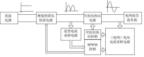
[0034] Such as figure 1 , image 3 , Figure 4 , Figure 5 As shown, the DC / AC grid-connected inverter circuit includes enhanced step-down chopper circuit, thyristor commutation circuit, inverter current sampling circuit, voltage and current detection circuit, thyristor commutation control circuit and SPWM control circuit .

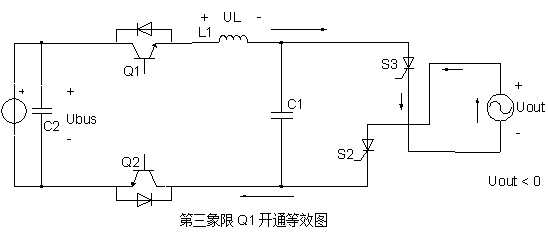
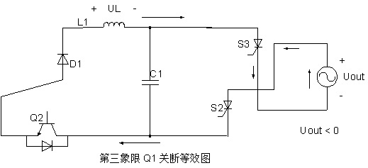
[0035] The enhanced step-down chopper circuit includes power switch Q1 (MOSFET or IGBT), power switch Q2 (MOSFET or IGBT), diode D1, diode D2, inductor L1 and capacitor C1, power switch Q1 drain (or collector ) is connected to the anode of the DC power supply and the cathode of the diode D2, its source (or emitter) is connected to one end of the inductor L1 and the cathode of the diode D1, and the drain (or collector) of the power switch tube Q2 is connected to the anode of the diode D2 and the capacitor C1 One end is connected to the cathode of the one-way thyristor S2 and S4 in the commutation circuit, its source (or emitter) is connected to the an...


PUM


Abstract

The invention relates to a DC/AC grid connected inverter circuit and a power factor adjusting method. The DC/AC grid connected inverter circuit comprises an enhanced voltage reduction chopper circuit and a controlled silicon power frequency phase inverter circuit, wherein the enhanced voltage reduction chopper circuit comprises an SPWM (Sinusoidal Pulse Width Modulation) modulated power switch tube, a double freewheel diode, a power factor adjusting power switch tube, an inductor and a capacitor. Direct current is converted into a half sine wave by adjusting the duty ratio of the high frequency switch tube in the enhanced voltage reduction chopper circuit; and power factor adjustment can be realized by adjusting the conduction mode of the power factor adjusting power switch tube. The direct current half sine wave is subjected to phase inversion by the phase inverter circuit composed of four low frequency controlled silicon to obtain a full sine wave so as to finish inversion from direct current to sine alternating current. Compared with the traditional full bridge grid connected inverter circuit, the grid connected inverter circuit provided by the invention is simple in structure, strong in overcurrent resistance, high in stability, high in inversion efficiency and low in cost, and the number of high frequency tubes is reduced by half. In the switching and phase inverting process, a constant common mode voltage is produced from the alternating current output of the inverter, so that the common mode current is inhibited and the EMI (Electro-Magnetic Interference) interference is reduced.

Description

[0001] technical field [0002] The invention relates to a grid-connected inverter circuit and a control method, in particular to a DC / AC grid-connected inverter circuit with high conversion efficiency, low harmonic distortion and power factor adjustment and an adjustment method. Background technique [0003] The function of the grid-connected inverter circuit is to convert the DC voltage into a sinusoidal AC, and realize grid-connected supply for electrical equipment. High efficiency and low harmonic distortion are the key indicators of this technology; when connecting to the grid for power generation, it is also necessary to adjust the power factor according to the power dispatching instruction. [0004] The existing grid-connected inverter technology mostly adopts a four-tube full-bridge circuit structure, such as figure 2 Shown, using bipolar modulation or unipolar modulation. In the bipolar modulation circuit, the four switching tubes (shown in the dotted line box) al...

Claims


Application Information

Patent Timeline
IPC IPC(8): H02M7/48H02M3/155H02M7/505H02J3/18
CPCY02E40/30
Inventor 牟英峰孙立峰徐鹏飞
Owner 牟英峰
Why Eureka
Try Eureka