Plasma cladding method and automatic cladding equipment for manufacturing wear resistant clad steel plate

A technology of plasma cladding and composite steel plate, which is applied in the coating process and coating of metal materials, can solve the problems of large denaturation of wear-resistant composite steel plate and easy cracking and falling of wear-resistant layer, so as to reduce deformation and benefit fully Metallurgical reaction, beneficial to the effect of weld surface forming

Inactive Publication Date: 2012-04-11
HARBIN INST OF TECH
View PDF4 Cites 4 Cited by
  • Summary
  • Abstract
  • Description
  • Claims
  • Application Information

AI Technical Summary

Problems solved by technology

The wear-resistant composite steel plate after surfacing welding by this process has great denaturation, and it needs to be leveled repeatedly. , the thickness of the base steel plate is limited to 10-14mm, suitable for surfacing one (one layer) wear-resistant layer

Method used


Image

  • Plasma cladding method and automatic cladding equipment for manufacturing wear resistant clad steel plate
  • Plasma cladding method and automatic cladding equipment for manufacturing wear resistant clad steel plate
  • Plasma cladding method and automatic cladding equipment for manufacturing wear resistant clad steel plate

Examples


Embodiment 1

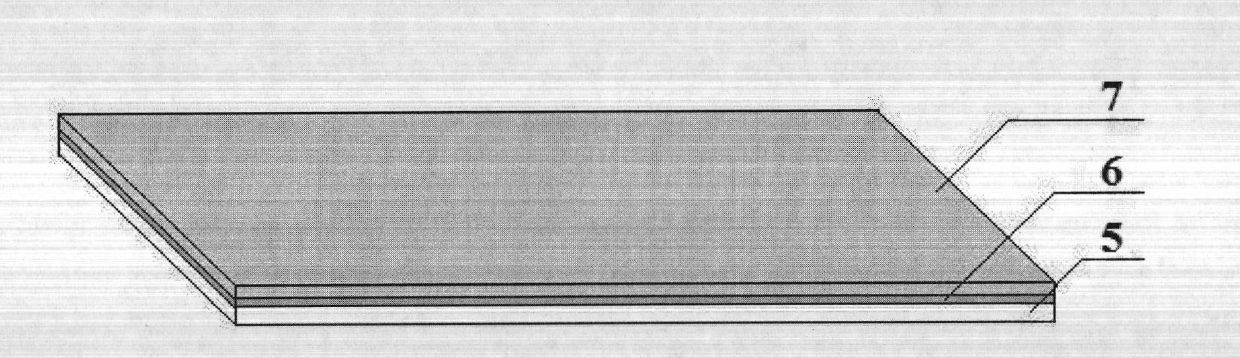
[0070] Example 1, taking the large-scale loading car liner in a mine as an example, the wear medium is ore, and the wear type is impact and abrasive wear. The size of each wear-resistant composite steel plate is required to be: length 3000mm × width 2000mm × thickness 15mm, of which Layer thickness (including fusion zone) ≥ 6mm, surface hardness HRC ≥ 60.

[0071] The Q345B plate with a length of 3100mm×width 2100mm×thickness of 10mm is selected as the base steel plate 5 (including the fixed part of the clamp), and a high-chromium cast iron type micro-slag wear-resistant alloy powder block material with a length of 80mm×width 30mm×thickness of 7mm is selected (the material available in the market) as the wear-resistant layer material.

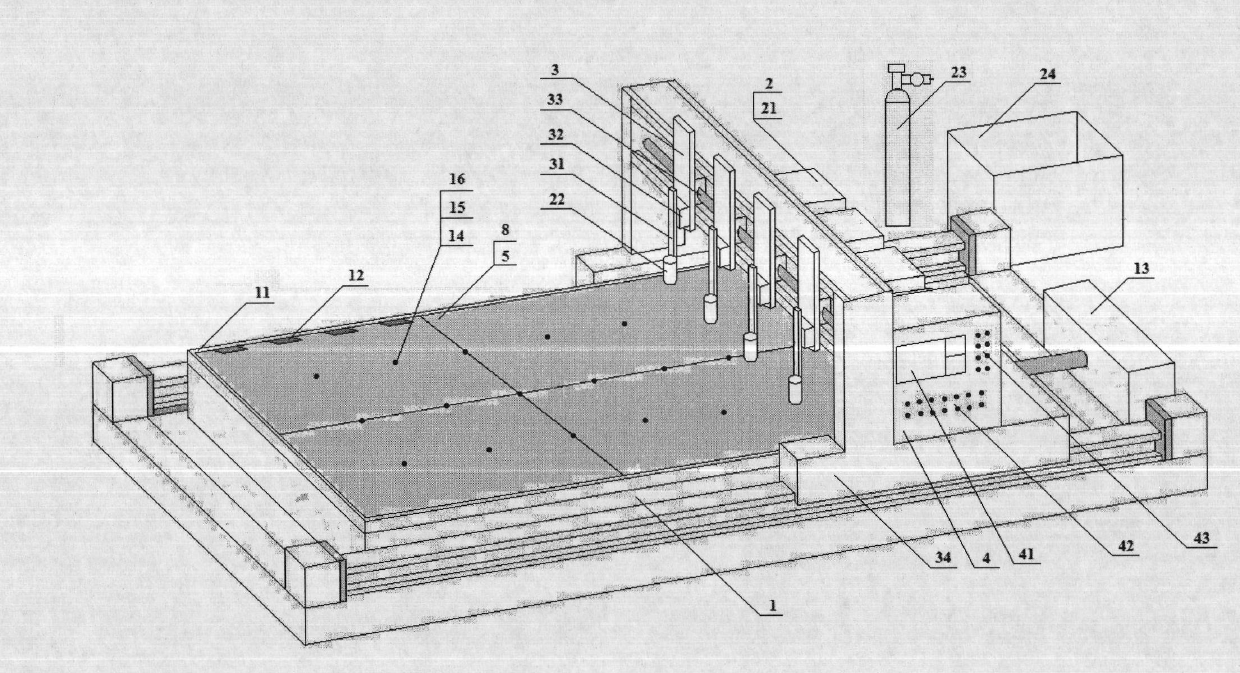
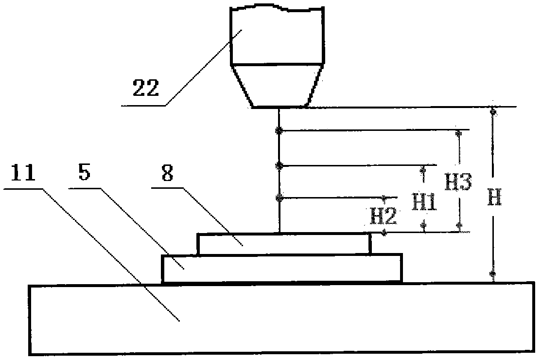
[0072] (1) The steps of the welding process technical scheme are as described above, and the operating trajectory and welding parameters are set as follows:

[0073] Plasma welding gun transverse gap swing width B: 45mm / each time, walking spee...

Embodiment 2

[0097] Embodiment 2, taking the waste discharge pipeline of a waste-to-energy plant as an example, the wear medium is dust, sand grains, iron chips, masonry blocks, the wear type is erosion wear, the pipe wall thickness is 20mm, and the side length is a square pipe with a side length of 600mm. The section length is 1000mm, and there are eight sections. At present, it is made of Q345B steel plate. After one month of use, the pipe wall is worn out and scrapped.

[0098]According to the use environment and wear type of the pipeline, considering the cost of the product, a Q235 plate with a length of 2500mm×width 2100mm×a thickness of 12mm is used as the base steel plate 5 (including the margin for pressing the four sides of the base plate by the clamp), and a length of 80mm× High chromium nickel tungsten carbide micro-slag wear-resistant alloy powder bulk material with a width of 30 mm × a thickness of 10 mm (the material is available in the market). Adopt the four-gun plasma clad...


PUM

PropertyMeasurementUnit
thicknessaaaaaaaaaa
thicknessaaaaaaaaaa
thicknessaaaaaaaaaa

Abstract

The invention relates to a plasma cladding method and automatic cladding equipment for manufacturing a wear resistant clad steel plate. The method is characterized by adopting a four-gun automatic plasma cladding method, selecting and spreading a wear resistant alloy powder bulk material with thickness being 3-15mm on a base steel plate, putting the base steel plate on a cast iron cladding table with thickness being 80-120mm, fixing the periphery of the base steel plate with the cast iron cladding table through platen clamps, fixing the middle part of the base steel plate with the cast iron cladding table through stop pins, utilizing high energy beam plasma arcs with nozzle aperture ratio being (0.75-0.85):1 as the cladding heat sources and utilizing four guns to synchronously and automatically clad the wear resistant alloy powder bulk material and metallurgically bond the wear resistant alloy powder bulk materials with the base steel plate. The method and the equipment have the following beneficial effects: the manufacturing cost is low; the production efficiency is high; the wear resistant clad steel plate with large area can be manufactured; and the obtained wear resistant clad steel plate has the characteristics of narrow fusion area, small deformation and good product quality.

Description

technical field [0001] The invention relates to a manufacturing method and equipment for wear-resistant composite steel plates, in particular to a plasma cladding method and plasma automatic cladding equipment for fabricating wear-resistant clad steel plates. Background technique [0002] Half of the steel in the machinery industry is used to make spare parts every year, and 80% of the failure of mechanical parts is caused by wear and tear. In the mining, metallurgy, cement, coal, electric power, petrochemical, transportation, machinery manufacturing and other industries, most of the production equipment in the process of use, due to the serious wear and tear of the parts, the key parts or the whole set of equipment, or even the whole line The production line cannot operate normally, and it needs to stop production frequently to replace parts or carry out maintenance, which directly affects the normal production order and brings great economic losses to the enterprise. There...

Claims


Application Information

Patent Timeline
Patent Type & Authority Applications(China)
IPC IPC(8): C23C24/10
Inventor 郭面焕刘爱国所春固所健彬郭毅
Owner HARBIN INST OF TECH
Why Eureka
Try Eureka