LED cooling module structure

A heat dissipation module and LED component technology, which is applied in the direction of electrical components, circuits, semiconductor devices, etc., can solve the problems of high cost, poor thermal conductivity of the overall composite substrate, poor mechanical shock resistance, etc., and achieve the best industrial economic benefits.

Inactive Publication Date: 2015-07-29
HO CHENG INDUSTRIAL CO LTD
View PDF35 Cites 0 Cited by
  • Summary
  • Abstract
  • Description
  • Claims
  • Application Information

AI Technical Summary

Problems solved by technology

[0006] The substrate of the LED has two requirements: the electrical conduction of the electrode and the heat conduction of the heat conduction contact. Although the metal material has high thermal conductivity, directly welding the electrode on the metal substrate will cause a short circuit, so the metal surface must be provided with an electrical insulation structure.
Insulating materials, except for diamond and nitride, have poor thermal conductivity and poor mechanical shock resistance. Therefore, if a high thermal conductivity insulating material substrate is used directly, there will be problems of high cost and poor mechanical endurance
If the printed circuit board is used as the substrate, the cost is low but the thermal conductivity is poor, so it cannot be used for high-brightness lighting applications
If the method of coating the surface of the metal substrate with an insulating film is limited by the poor thermal conductivity of the coating, the thermal conductivity of the overall composite substrate is relatively poor

Method used


Image

  • LED cooling module structure
  • LED cooling module structure
  • LED cooling module structure

Examples


Embodiment Construction

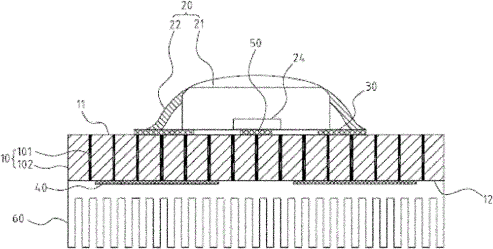
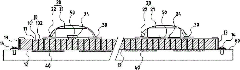
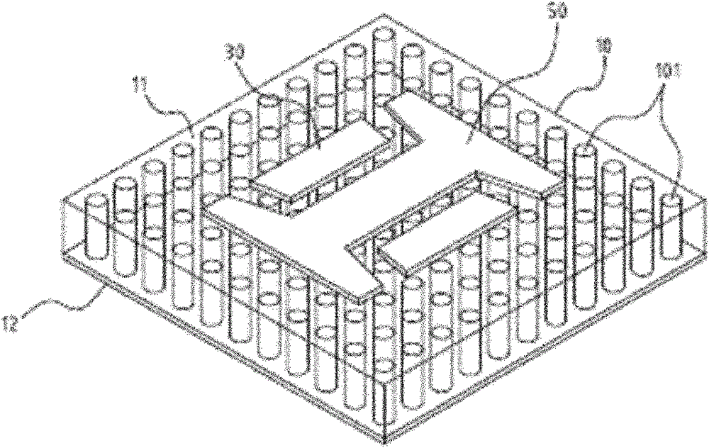
[0018] Figure 1 to Figure 3 Shown is a preferred embodiment of the heat dissipation module structure of the LED of the present invention, but this embodiment is only for illustration, and the scope of patent protection is not limited by this structure; the heat dissipation module structure of the LED (light emitting diode) includes:

[0019] A composite heat conduction substrate 10 is a plate-shaped body formed by combining a plurality of heat conduction wires 101 and insulating material 102, which has a front surface 11 and a back surface 12, wherein the heat conduction wires 101 are spaced apart from each other, and the conduction wires The heating wire 101 runs through the front side 11 and the back side 12, and the heating wires 101 are separated by an insulating material 102;

[0020] At least one LED component 20 is combined with the front surface 11 of the composite heat-conducting substrate 10, and the LED component 20 includes an LED component 21 and an electrode pin ...


PUM


Abstract

The invention provides a heat-conducting substrate and a radiating module structure of an LED (light-emitting diode). The heat-conducting substrate comprises a composite-material heat-conducting substrate formed by combination of a plurality of heat-conducting lines or fibers and an insulating material; the heat-conducting lines or fibers are distributed at intervals, penetrate through the front surface and the back surface of the composite-material heat-conducting substrate and are separated by the insulating material; electrode welding pads are combined on the front surface of the composite-material heat-conducting substrate so as to form electric connection with electrode pins of an LED member, and heat-conducting welding pads are also combined on the front surface of the composite-material heat-conducting substrate so as to form heat-conducting contact with heat-sink parts of an LED component of the LED member; and insulating layers corresponding to the electrode welding pads are combined on the back surface of the composite-material heat-conducting substrate. In the invention, the characteristics with high heat conductivity in the thickness direction but insulation in the plane direction can be achieved by a simple structure, so that the heat can be quickly conducted to a radiating member. The invention can be used for high-brightness LED illuminating products.

Description

technical field [0001] The invention relates to a heat dissipation module structure of an LED (light-emitting diode); in particular, a heat-conducting substrate structure with high heat conduction in the thickness direction and insulation in the plane direction is formed by using a heat conduction wire of a metal material and an insulating material. Background technique [0002] In the actual use of LEDs, the conversion efficiency of electric energy and light energy is still low, resulting in the generation of heat when they work. Among them, for high-power LEDs used with high brightness, the heat generated is higher. If the heat cannot be exported , The temperature of the LED will rise accordingly, which will cause color shift, and eventually cause the LED to deteriorate and fail to work. [0003] Heat dissipation has always been the focus of LED design, which mainly conducts heat energy to the heat exchanger through heat-conducting materials, and then dissipates heat energ...

Claims


Application Information

Patent Timeline
Patent Type & Authority Patents(China)
IPC IPC(8): H01L33/64H01L33/48
Inventor 张义顺郑世裕
Owner HO CHENG INDUSTRIAL CO LTD
Why Eureka
Try Eureka