Micro drill and processing method thereof

A micro drill bit and drill tip technology, which is used in metal processing equipment, drill repair, drilling tool accessories, etc., can solve the problems of poor surface roughness and easy damage of the hole wall, improve the surface roughness of the hole wall and reduce cutting The effect of strength and cutting thickness reduction

Active Publication Date: 2013-09-11
SHENZHEN JINZHOU PRECISION TECH
View PDF9 Cites 4 Cited by
  • Summary
  • Abstract
  • Description
  • Claims
  • Application Information

AI Technical Summary

Problems solved by technology

As the drilling diameter requirements of micro-drills become smaller and smaller, small drills are more likely to be damaged due to cutting strength and long-term cutting. In addition, because the cutting edge of the drill is generally cut at one time, the surface roughness of the formed hole wall is relatively high. Difference

Method used


Image

  • Micro drill and processing method thereof
  • Micro drill and processing method thereof
  • Micro drill and processing method thereof

Examples


Embodiment 1

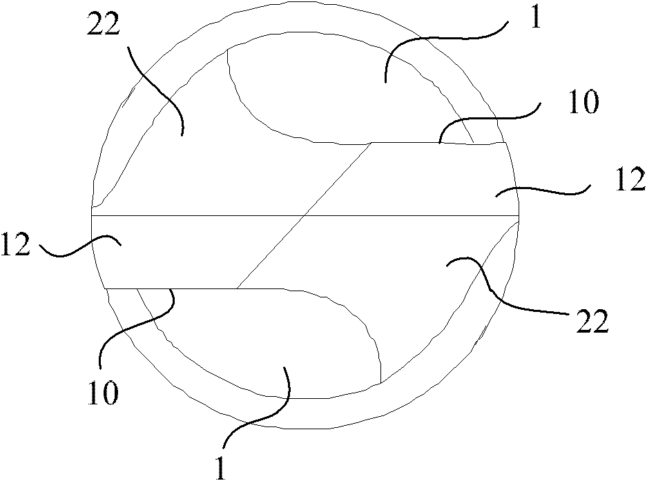
[0032] like Figure 4 As shown, the drill tip portion of the drill bit has four cutting edges, which are respectively two first cutting edges 10 corresponding to the flutes 1 and two second cutting edges 20 formed on the first relief surface 12, The second rake face 21 intersects with the second flank face 22 to form the second cutting edge 20, and the second rake face 21 intersects with the first flank face 12. In this embodiment, the second rake face 21 and the first flank 12 are connected by a curved surface, so that the strength of the intersection of the two flanks can be improved, and the curved surface is conducive to the discharge of debris. like Figure 5 As shown, the two second cutting edges 20 respectively intersect with the chisel edge 30 at the apex of the drill point, so that the second rake face 21 is in a triangular shape, so that when drilling, in addition to the extrusion of the chisel edge 30, there are also The cutting effect of the second cutting edge 2...

Embodiment 2

[0035] like Figure 7 Shown is the second embodiment of the present invention, different from the first embodiment, the second cutting edge 20 of the second embodiment does not intersect with the chisel edge 30 at the apex of the drill point, so that when drilling The chisel edge 30 is still in the extruded state, so as to prevent the second cutting edge 20 from participating in drilling extrusion and causing excessive wear. However, the accuracy of the hole position formed by drilling in this solution is lower than that of the solution in Embodiment 1.

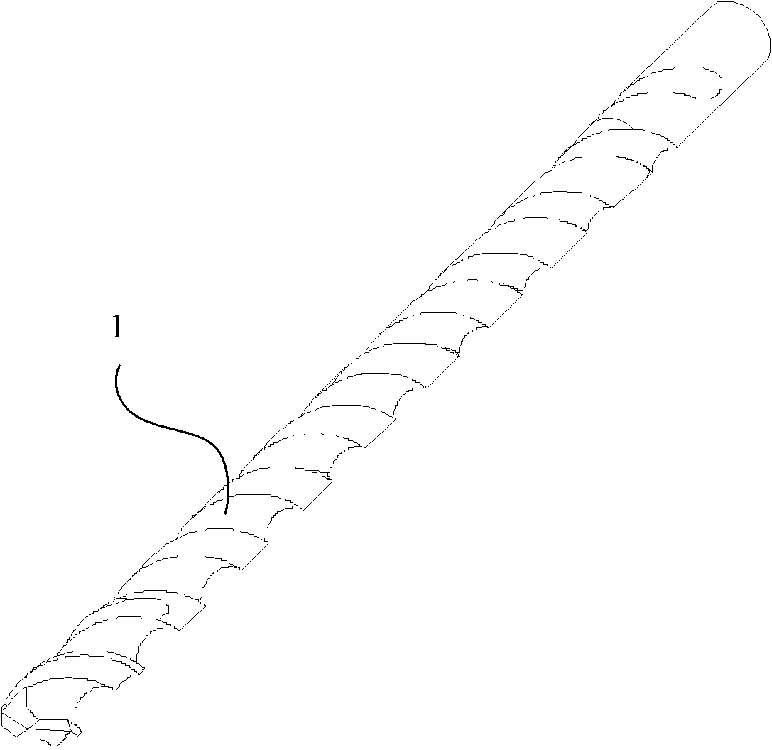
[0036] In two embodiments of the present invention, the drill bit is provided with a shovel back, such as Figures 4 to 8 As shown, the setting position of the shovel back corresponds to the second relief surface 22 and extends downward along the flute 1 according to its helix angle.

[0037] Of course, the above two embodiments are the situation where the second cutting edge intersects the chisel edge. According to the ide...


PUM


Abstract

The invention discloses a micro drill and a processing method thereof. The micro drill comprises a chisel edge, two first cutting edges, two first rear knife faces corresponding to the two first cutting edges, two second cutting edges, and two second front knife faces and two second rear knife faces corresponding to the two second cutting edges, wherein two chip removal grooves which are spiral along a drill body correspond to the two first cutting edges; the second front knife faces are formed between the first rear knife faces and the second rear knife faces; the second cutting edges are formed at junctions of the second front knife faces and the second rear knife faces; and the included angle of the second cutting edges relative to a cutting plane is smaller than that of the first cutting edges relative to the cutting plane. Two cutting edges are formed at the drill tip of the drill additionally, and the included angle of the cutting edges relative to the cutting plane is smaller than that of the first cutting edges relative to the cutting plane, so that the cutting service life of the drill is prolonged; in addition, the formed cutting edges are relatively thin, so that the chip removal unobstructed property is improved, and the surface roughness of a hole wall is improved.

Description

technical field [0001] The invention relates to the field of cutting processing, and more specifically, relates to a micro drill bit and a processing method thereof. Background technique [0002] With the development of printed circuit board (PCB) technology and products, the demand for cemented carbide drills is increasing year by year, new cemented carbide drills continue to appear, and the requirements for cemented carbide drills are also getting higher and higher. Tungsten carbide drill for PCB (referred to as PCB micro-drill) is a micro-hole processing tool with a complex shape and a spiral groove, which is derived from the traditional twist drill. PCB micro-drills are tiny in size, and the drill tip structure can only be observed with the help of an optical microscope. At present, most PCB manufacturers use CNC drilling machines to process PCB boards. CNC drilling is an important part of the printed board manufacturing process, and carbide drills are the key factors t...

Claims


Application Information

Patent Timeline
Patent Type & Authority Patents(China)
IPC IPC(8): B23B51/00B24B3/24
Inventor 郭强付连宇
Owner SHENZHEN JINZHOU PRECISION TECH
Why Eureka
Try Eureka