

Fiber winding prestress turbine rotor
A turbine rotor and prestressing technology, which is applied to the support components of blades, climate sustainability, engine components, etc., can solve the problems of steel wire strength decline and the inability to meet the high temperature working environment of turbine rotors, so as to reduce working stress and improve fatigue Effect of lifetime or operating temperature
- Summary
- Abstract
- Description
- Claims
- Application Information
AI Technical Summary
Problems solved by technology
Method used
Image

Examples
Embodiment 1
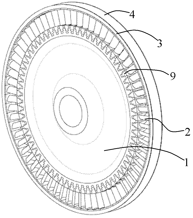
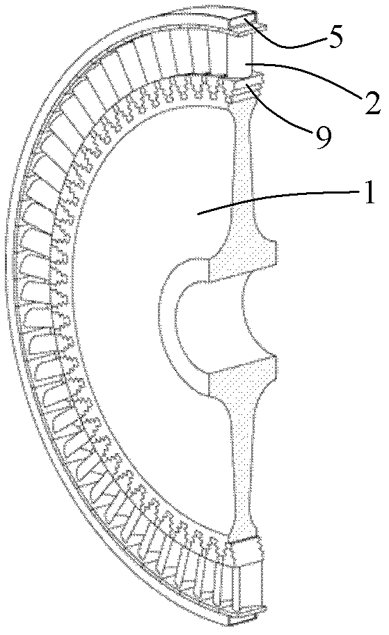
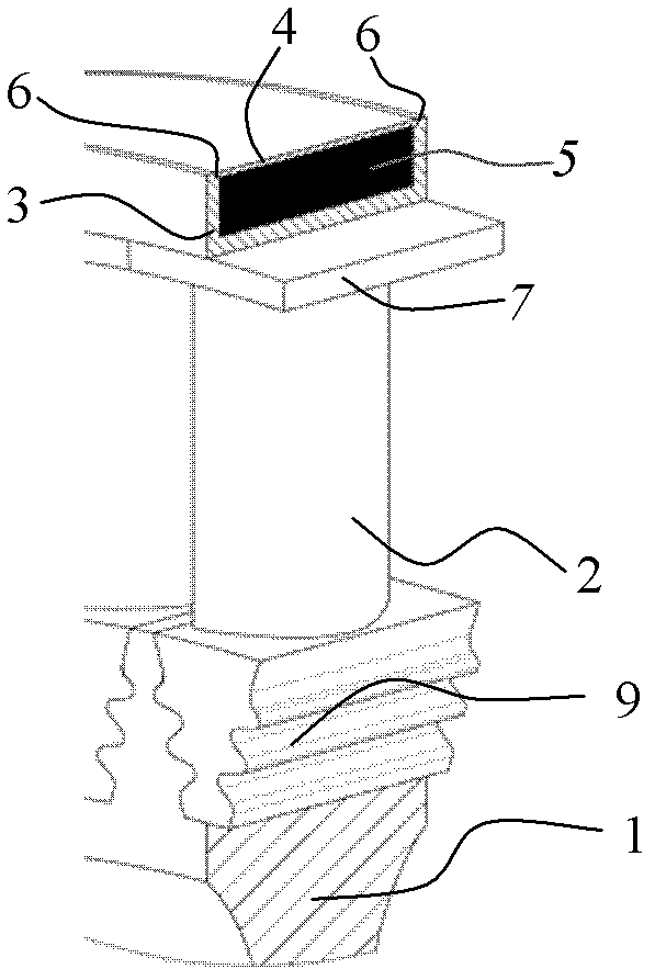
[0037] The specific structure of a prestressed fiber wound turbine rotor of the present invention is as follows: figure 1 , figure 2 with image 3 shown. The turbine rotor consists of a turbine disc 1 and a set of blades 2, which are assembled with a light-weight high-temperature-resistant material (such as titanium-aluminum intermetallic compound or carbon / carbon composite material) outside the blade shroud 7 with a gap of 0.001mm to 0.01mm. The ring groove 3 is made, and the high-temperature high-strength fiber is wound in the ring groove 3 layer by layer with a tensile stress of 0-10.0GPa; when the preset number of turns and layers are wound, the prestressed fiber winding layer 5 The thickness can reach 0.5mm ~ 100mm. After the preset prestress is generated on the turbine disk 1 and blade 2, the winding layer is covered with a sealing cover plate 4, and a closed structure is formed by connecting the seam 6 and the ring groove 3 to isolate the prestress. The stress windi...
Embodiment 2
[0039] The specific structure of a prestressed fiber wound turbine rotor of the present invention is as follows: Figure 4 with Figure 5 shown. The turbine rotor is composed of a turbine disk 1 and a set of blades 2. The winding groove 8 is directly processed on the blade crown 7 of the blade, and the high-temperature and high-strength fibers are wound on the winding groove layer by layer with a tensile stress of 0-10.0GPa. 8; when the preset number of turns and layers are wound, the thickness of the prestressed fiber winding layer 5 can reach 0.5 mm to 100 mm. After the preset prestress is generated on the turbine disk 1 and blade 2, seal the The plate 4 covers the wrapping layer and forms a closed structure through the connection of the seam 6 and the wrapping groove 8 to isolate the prestressed wrapping layer 5 from contact with the external airflow.
Embodiment 3
[0041] The specific structure of a prestressed fiber wound turbine rotor of the present invention is as follows: Image 6 with Figure 7 shown. The turbine rotor is composed of a turbine disk 1 and a set of blades 2. The winding groove 8 processed on the blade crown 7 of the blade is made of fibers (silicon carbide fibers) with strong high-temperature oxidation resistance or reliable oxidation resistance on the surface. Coated (such as carbon fiber surface prepared with silicon carbide coating or aluminum oxide coating) fibers are wound in the winding groove 8 layer by layer with a tensile stress of 0-10.0 GPa. After the preset number of turns and layers are wound, the thickness of the prestressed fiber winding layer 5 can reach 0.5 mm to 100 mm, and a preset prestress is generated on the turbine disk 1 and the blade 2 .
PUM
 Abstract
Description
Claims
Application Information