
Heat pipe type end milling cutter

An end mill and heat pipe type technology, applied in the field of cutting processing, can solve the problems of reduced rigidity of the connection between the spindle and the tool holder, increased cost of cutting fluid, and affected machining accuracy, etc., to improve cutting stability, easy maintenance, and flexible use. Effect

Inactive Publication Date: 2012-05-02
SHANDONG UNIV
View PDF2 Cites 4 Cited by
  • Summary
  • Abstract
  • Description
  • Claims
  • Application Information

AI Technical Summary

Problems solved by technology

Since the high-speed cutting system is a complex dynamic system, with the increase of cutting speed, under the influence of centrifugal force and gyroscopic effect, the clamping force between the spindle and the tool holder will decrease significantly, resulting in the coupling stiffness between the spindle and the tool holder. Reduced, affecting machining accuracy
[0003] On the other hand, in high-speed cutting, as the material removal rate increases sharply, the energy consumed in the machining process also rises sharply. More than 90% of this energy is converted into heat and accumulated at the tip of the tool. If the heat cannot be transmitted in time, will quickly cause the tool to fail
The traditional method is to use cutting fluid to reduce the temperature of the cutting zone, but the use of cutting fluid increases the cost and the sulfur, phosphorus and other components contained in the cutting fluid will pollute the environment

Method used


Image

  • Heat pipe type end milling cutter
  • Heat pipe type end milling cutter
  • Heat pipe type end milling cutter

Examples


Embodiment Construction

[0017] The present invention will be further described below in conjunction with the accompanying drawings and embodiments.

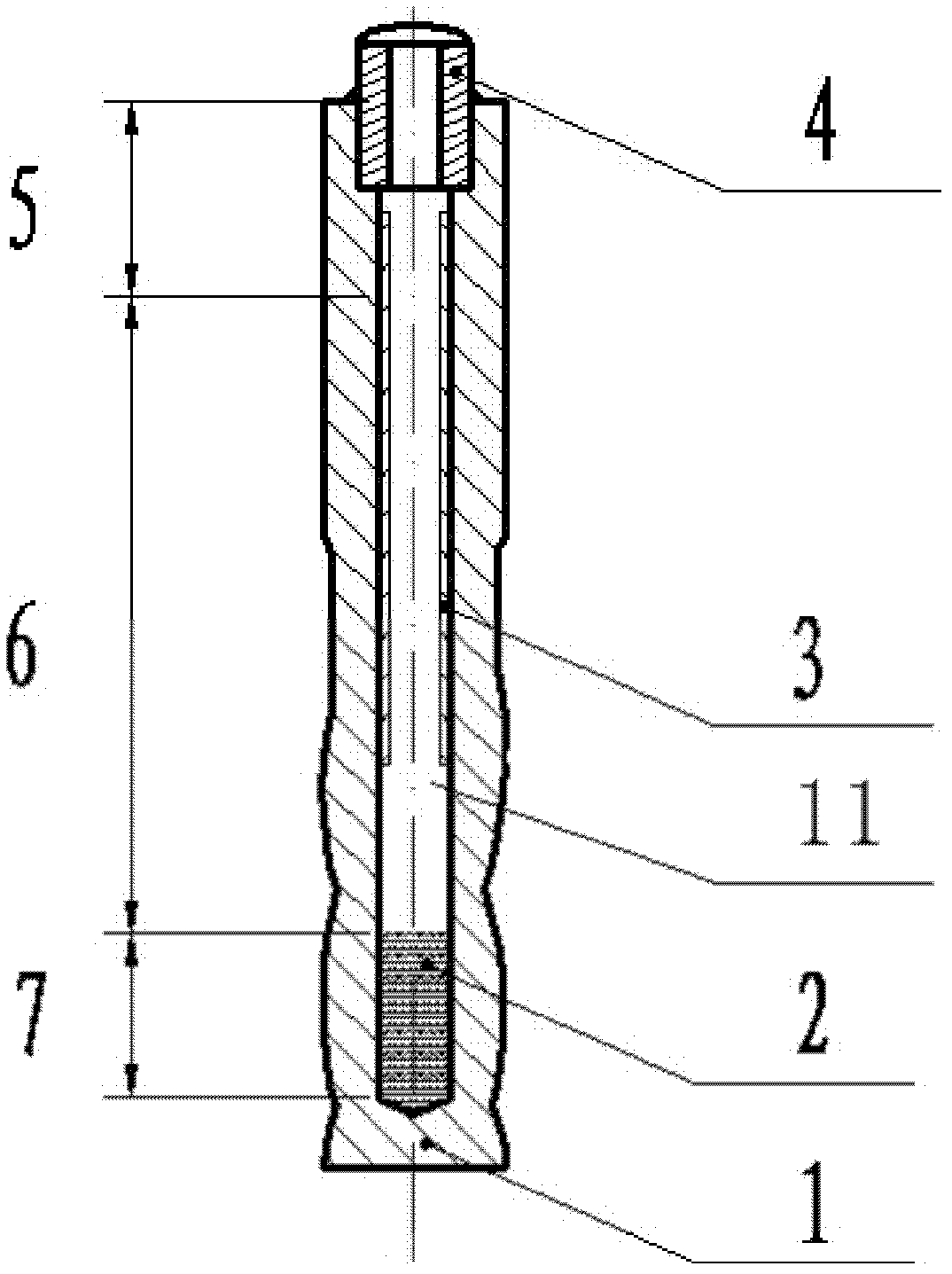
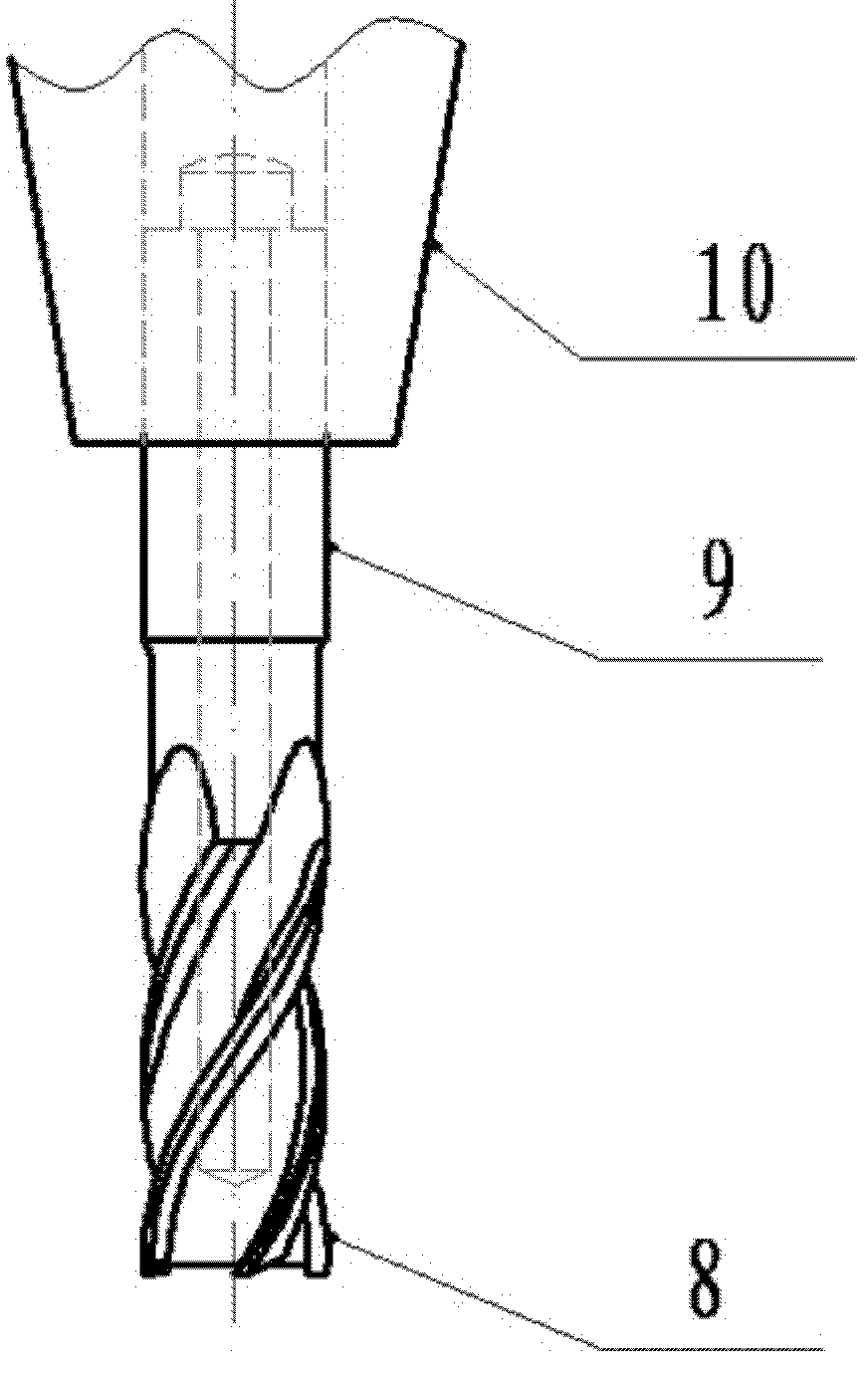
[0018] Such as figure 1 , 2 As shown, a heat pipe type end mill 1 includes a tool bar 9, the center of the tool bar 9 is provided with an axial blind hole 11, the opening end of the blind hole 11 faces the handle 10, and the blind hole 11 A liquid-absorbing core 3 is attached to the inner wall, and the opening end of the blind hole 11 is sealed with a sealing tube 4. A part of the liquid working medium 2 is housed in the blind hole 11, and the blind hole 11 is in a vacuum state.

[0019] The blind hole 11 is divided into three sections along the axial direction, the section near the milling cutter tip filled with liquid working medium 2 is the evaporation section 7 , the section near the opening end of the blind hole is the condensation section 5 , and the middle section is the adiabatic section 6 .

[0020] The liquid-absorbing core 3 is arranged in ...


PUM


Abstract

The invention discloses a heat pipe type end milling cutter which comprises a cutter bar; an axial blind hole is arranged in the center of the cutter bar; the opening end of the blind hole faces a cutter handle; a liquid absorbing core is adhered to the inner wall of the blind hole; the opening end of the blind hole is sealed by using a seal pipe; a part of liquid working medium is filled in the blind hole; and the blind hole is in vacuum state. According to the technical scheme put forward by the invention, cutting heat generated in the cutting process can be rapidly transferred to the cutter handle by the working medium, the accumulation of heat on a cutter point is avoided, meanwhile, the connection rigidity between a main shaft and the cutter handle is increased as the cutter handle is affected by the heat to expand; and the heat pipe type end milling cutter has the characteristics of intensified heat transfer, increasing of cutting stability, simple structure, flexibility in use, convenience to maintain, cost reduction and the like.

Description

technical field [0001] The invention relates to a cutting processing field, in particular to a heat pipe type end mill. Background technique [0002] As an important part of advanced manufacturing technology in the 21st century, high-speed cutting technology characterized by high cutting speed, high feed speed and high machining accuracy has been widely used in many fields such as aerospace, automobiles, machine tools, molds, etc. . Since the high-speed cutting system is a complex dynamic system, with the increase of cutting speed, under the influence of centrifugal force and gyroscopic effect, the clamping force between the spindle and the tool holder will decrease significantly, resulting in the coupling stiffness between the spindle and the tool holder. Reduced, affecting the machining accuracy. [0003] On the other hand, in high-speed cutting, as the material removal rate increases sharply, the energy consumed in the machining process also rises sharply. More than 90%...

Claims


Application Information

Patent Timeline
IPC IPC(8): B23C5/10B23C5/28
Inventor 唐委校宋清华鞠华伟
Owner SHANDONG UNIV
Learn More