Waste heat recovering device of high-temperature metallurgy slag particles

A waste heat recovery device and metallurgical slag technology, which is applied in the field of waste heat recovery in the metallurgical industry, can solve the problems of secondary energy loss, high power consumption, and high investment costs, and achieve the goals of improving output and quality, realizing uniform heat exchange, and ensuring uniformity Effect

Active Publication Date: 2012-05-02
NORTHEASTERN UNIV
View PDF4 Cites 26 Cited by
  • Summary
  • Abstract
  • Description
  • Claims
  • Application Information

AI Technical Summary

Problems solved by technology

[0004] Aiming at the disadvantages of the waste heat recovery process of dry granulation of metallurgical slag, such as large air-slag ratio, high power consumption, secondary energy loss, and high investment cost, the present invention provides a high-temperature metallurgical slag waste heat recovery device, including an intermediate hopper, a boiler furnace Body, steam drum, superheater, evaporator, economizer and discharge machine, the middle hopper is set above the inlet of the boiler body, the boiler body is a welded rectangular furnace shell, and the built-in refractory material forms a rectangular cavity , fixed on the boiler bracket, the boiler furnace body is divided into storage section and working section from top to bottom, the height of the storage section is 1 / 4~1 / 2 of the height of the working section, and the superheater, evaporator, and economizer are arranged from the top Arranged in the working section from bottom to bottom, they are composed of single or multiple heat exchange tube groups. Each heat exchange tube group is composed of single or multiple boiler heat exchange tubes. The two ends of the heat exchange tubes are respectively connected to the heat exchange On the inlet header and outlet header of the pipe group, the inlet header is connected to the distribution header through the distribution pipe, and the outlet header is connected to the collection header through the collection pipe. The inlet end of the economizer is connected to a water pump, and the outlet end is connected to the The steam drum is connected to the inlet of the superheater, and the distribution header is connected to the distribution header through the circulating water pump, the collection header is connected to the steam drum, and the outlet of the superheater is connected to the steam pipe network or steam turbine; a discharge machine is installed at the boiler outlet

Method used


Image

  • Waste heat recovering device of high-temperature metallurgy slag particles
  • Waste heat recovering device of high-temperature metallurgy slag particles
  • Waste heat recovering device of high-temperature metallurgy slag particles

Examples


Embodiment Construction

[0020] The present invention will be further described below in conjunction with the accompanying drawings and embodiments.

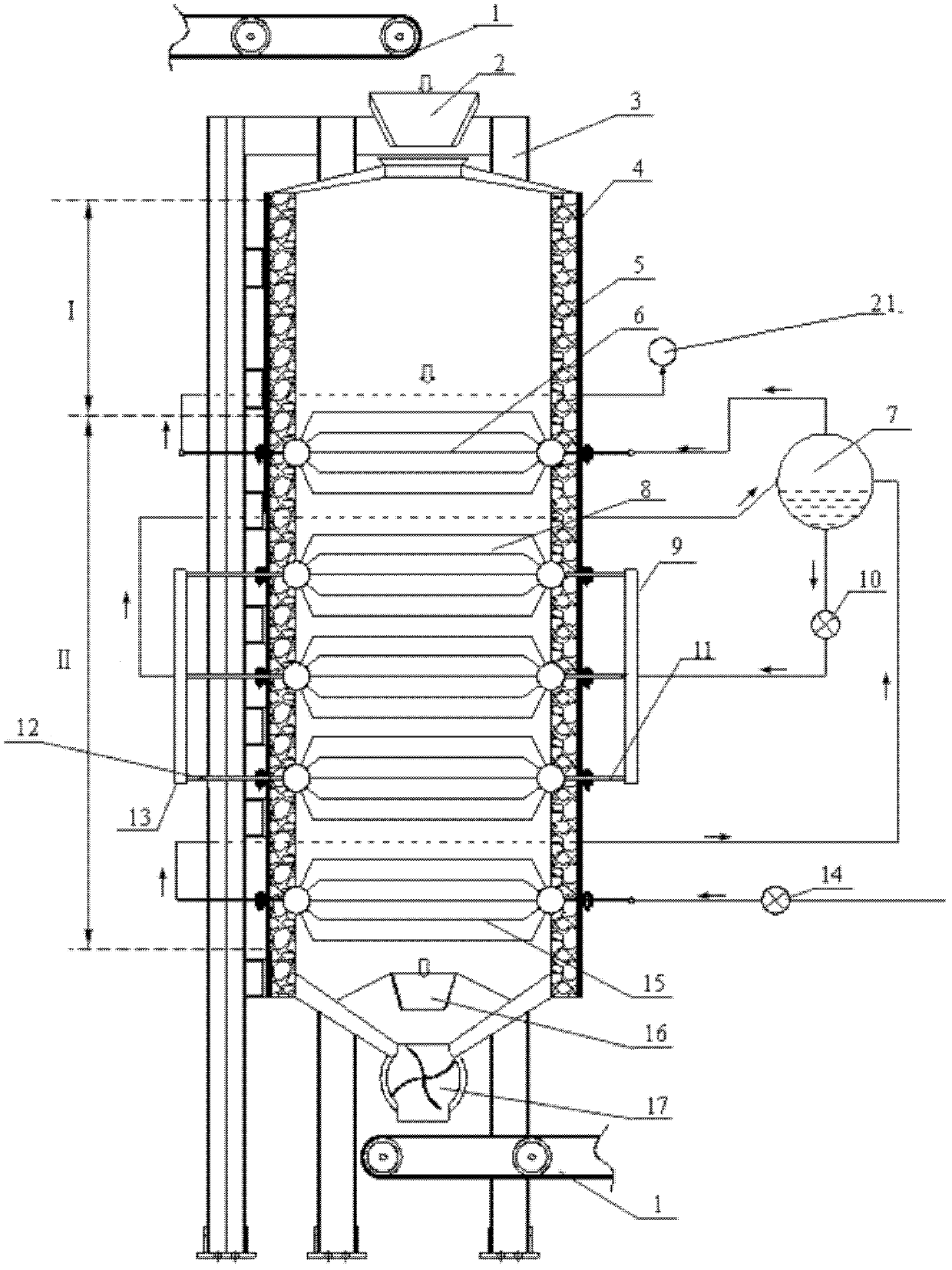
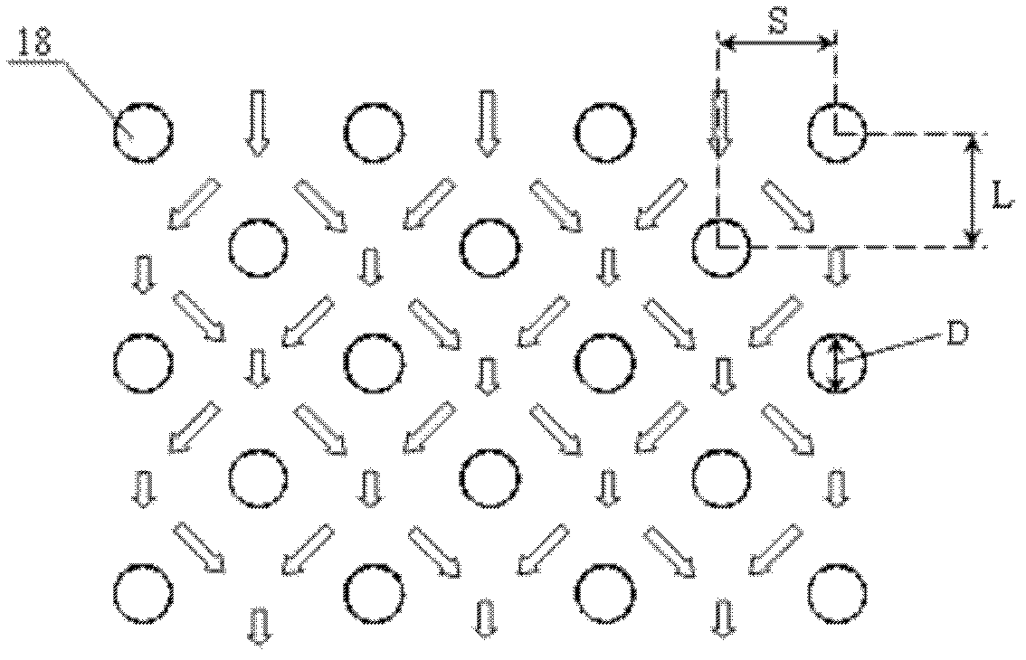
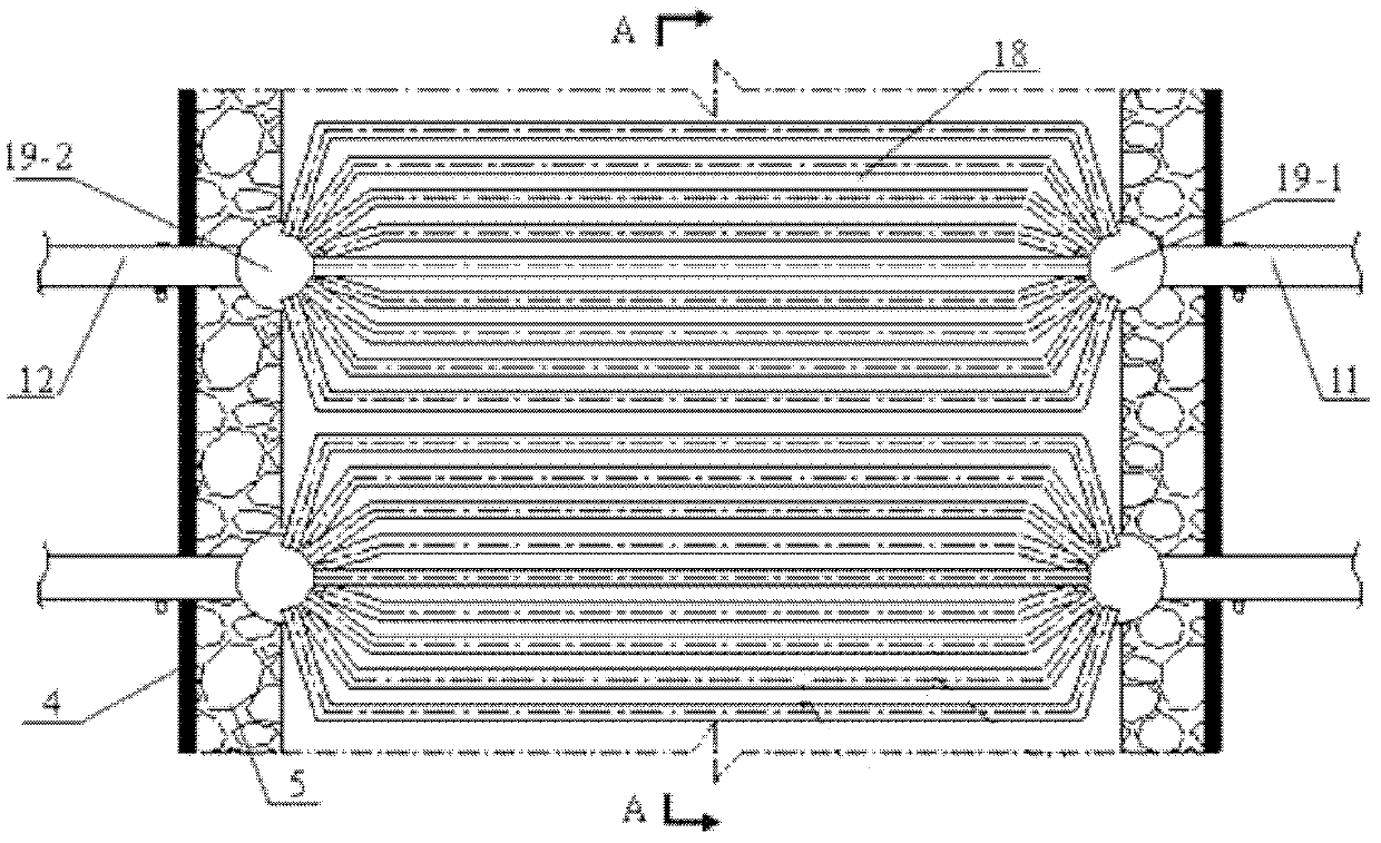
[0021] High-temperature metallurgical slag waste heat recovery device, including intermediate hopper 2, boiler furnace body, steam drum 7, superheater 6, evaporator 8, economizer 15 and discharger 17, the intermediate hopper 2 is set at the inlet of the boiler furnace body Above, the boiler furnace body is a rectangular furnace shell 4 welded by stainless steel plates. The built-in refractory material 5 forms a rectangular cavity and is fixed on the boiler bracket 3. The boiler furnace body is divided into storage section I and working section II from top to bottom. The height of the storage section I is 1 / 4~1 / 2 of the height of the working section II, and the superheater 6, the evaporator 8, and the economizer 15 are sequentially arranged in the working section II from top to bottom, and a superheater is provided in this embodiment 6. Three evaporators...


PUM


Abstract

The invention provides a waste heat recovering device of high-temperature metallurgy slag particles. The device comprises a middle hopper, a boiler body, a steam pocket, a superheater, an evaporator, an economizer and a discharging machine, wherein the middle hopper is arranged above the material inlet of the boiler body; a refractory material is arranged in the boiler body and a rectangle cavityis formed; the boiler body is divided into a storage section and a work section from top to bottom; the superheater, the evaporator and the economizer are successively arranged in the work section from top to bottom and respectively consist of single or multiple heat exchange pipe groups; the two ends of each heat exchange pipe are respectively connected to a water inlet header and a water outletheader of each heat exchange pipe group; the water inlet header is connected with an distribution header through a distribution pipe; the water outlet header is connected with a converge header through a converge pipe; the steam pocket is connected with the water outlet header; the outlet end of the superheater is connected with a steam pipe network or steam turbine; and the discharging machine is installed at the outlet of the boiler. By using the waste heat recovering device, uniform heat exchange can be realized, the yield and the quality of the steam are improved, and the recovery efficiency of waste heat is high.

Description

technical field [0001] The invention belongs to the technical field of waste heat recovery in the metallurgical industry, and in particular relates to a waste heat recovery device for high-temperature metallurgical slag particles. Background technique [0002] Metallurgical slag (such as blast furnace slag, nickel slag, copper slag, alloy slag) is a by-product discharged during the metal smelting process. Its discharge temperature is relatively high and contains a large amount of waste heat and energy. Metallurgical slag dry granulation waste heat recovery process is a process in which metallurgical slag is in direct or indirect contact with heat transfer medium for granulation and waste heat recovery without consuming new water. This process can not only recover waste heat of metallurgical slag with high quality , and does not consume slag washing water, almost no harmful gas is discharged, which reduces the environmental pollution caused by the treatment of metallurgical s...

Claims


Application Information

Patent Timeline
Patent Type & Authority Applications(China)
IPC IPC(8): C21B3/04F27D17/00
CPCY02P10/25Y02W30/50
Inventor 于庆波刘军祥胡贤忠秦勤
Owner NORTHEASTERN UNIV
Why Eureka
Try Eureka