Differential testing method of power density distribution of electron beam

A technology of electron beam current and power density, which is applied in the direction of radiation measurement, measuring device, X/γ/cosmic radiation measurement, etc. It can solve the problems of affecting measurement accuracy, large measurement error, and easy blocking of small holes by metal, and achieves The effect of improving measurement accuracy and saving test cost

Active Publication Date: 2012-05-02
NANJING UNIV OF SCI & TECH
View PDF2 Cites 21 Cited by
  • Summary
  • Abstract
  • Description
  • Claims
  • Application Information

AI Technical Summary

Problems solved by technology

Among them, the small beam empirical method can only roughly determine the focus position, and the operator's experience has a greater influence; the Arata-Beam Teat Method (AB method) invented by Professor Arata of Japan is to place metal sheets vertically at different heights, in a Sawtooth slope shape, the electron beam sweeps along the slope, by measuring the traces of the electron beam melting width on the metal sheet, the space diameter and focus position of the electron beam at different working distances are measured, the measurement error of the melting width is large; the probe type The test method is only suitable for the measurement of small power density du

Method used


Image

  • Differential testing method of power density distribution of electron beam
  • Differential testing method of power density distribution of electron beam
  • Differential testing method of power density distribution of electron beam

Examples


Embodiment Construction

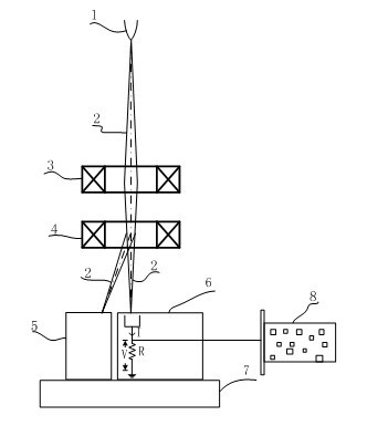
[0021] combine figure 1 , the differential test method of electron beam current power density distribution of the present invention, the steps are as follows:

[0022] 1.1 Layout of the test system. The test system includes an electron beam welder, an energy absorbing device 5, a Faraday cage sensor 6, and an industrial computer. The electron beam welder includes an electron beam emitting cathode 1, a focusing coil 3, a deflection coil 4, a workbench 7 and Welding machine control system, the electron beam current 2 is generated by the electron beam emitting cathode 1 in the electron gun, the focusing coil 3 and the deflection coil 4 are coaxial, the focusing coil 3 is above the deflection coil 4, the energy absorbing device 5 and the Faraday cup sensor 6 are installed on On the workbench 7, the Faraday cage sensor device 6 is located directly below the deflection coil 4 of the electron beam welder, the energy absorbing device 5 is placed on the left side of the Faraday cage s...


PUM


Abstract

The invention discloses a differential testing method of power density distribution of an electron beam. The differential testing method comprises the following steps: firstly arranging a testing system; designing a Faraday cup sensor; enabling the electron beam to move along a path which is parallel to the length direction of a slit, wherein the path is a forward stroke scanning path, and signals acquired during the process are effective signals and are used for follow-up processing; enabling the electron beam to move in reverse direction after the electron beam completely passes through theslit, wherein the path is a reverse stroke scanning path, and the signals acquired during the process are invalid signals and are not stored; repeating the steps and enabling projection spots of the electron beam on a tungsten sheet to move from one side to the other side of the slit; setting a current density distribution function of the electron beam as f(x,y), and then getting a power density distribution function g(x,y) which equals f(x,y)*Ua; and performing forward stroke scanning n times during the whole deflection scanning, then getting n fi(x)s, using computer software to draw the n fi(x)s into a current density distribution graph and finally getting a power density distribution graph and the diameter. The differential testing method disclosed by the invention does not need to usea new metal test sample to measure power density distribution every time, thereby saving the testing cost.

Description

technical field [0001] The invention belongs to the technical field of electron beam processing, in particular to a differential test method for electron beam power density distribution. Background technique [0002] For an electron beam welding machine, in order to study the difference between the theoretical design and the actual electron gun, the influence of factors such as the stability of the electron gun power supply system and the change of vacuum degree on the diameter of the electron beam spot and the distribution of power density, and the effect of the size and position of the beam spot on The influence of weld seam formation needs to study the characteristics of the beam accurately, and quantitatively measure the position, diameter and distribution of the beam power density of the electron beam focus. [0003] At present, there are small beam current empirical method, AB test method, probe test method, threshold power density test method and DIABEAM test method (...

Claims


Application Information

Patent Timeline
IPC IPC(8): G01T1/29
Inventor 姜嘉赢王克鸿周琦彭勇朱军
Owner NANJING UNIV OF SCI & TECH
Why Eureka
Try Eureka