Improved combination structure and combining method of baseplate and heat dissipating structure

A heat dissipation structure and substrate technology, applied in the direction of electrical components, electrical solid devices, circuits, etc., can solve problems such as difficult welding, and achieve the effect of improving the overall heat transfer coefficient

Inactive Publication Date: 2012-05-09
PARAGON TECH
View PDF6 Cites 4 Cited by
  • Summary
  • Abstract
  • Description
  • Claims
  • Application Information

AI Technical Summary

Problems solved by technology

However, except for the copper base plate, which has metal weldability, the base plate and heat dissipation fins can be directly welded to improve heat dissipation efficiency, and the other two types of carrier plates have the problem of difficult soldering.

Method used


Image

  • Improved combination structure and combining method of baseplate and heat dissipating structure
  • Improved combination structure and combining method of baseplate and heat dissipating structure
  • Improved combination structure and combining method of baseplate and heat dissipating structure

Examples


Embodiment 1

[0052] Example 1: Ceramic Substrate

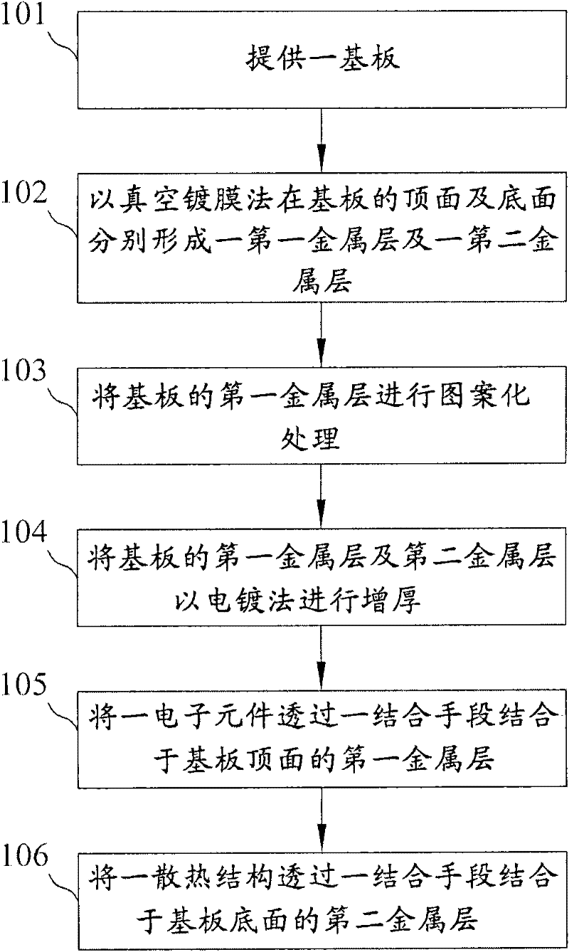
[0053] see figure 1 , is a flow block diagram showing the combination method of the substrate and the heat dissipation structure in this embodiment. and can also refer to Figure 2A ~ Figure 2F , is a diagram showing the various steps. The method of the present embodiment comprises the following steps:

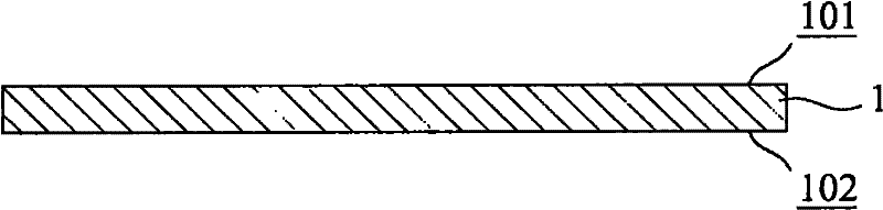
[0054] A substrate 1 is provided (step 101). The substrate 1 in this embodiment is a ceramic substrate, for example, it can be a commonly used ceramic substrate such as an alumina substrate, an aluminum nitride substrate, a silicon carbide substrate or a beryllium oxide substrate (see Figure 2A ).

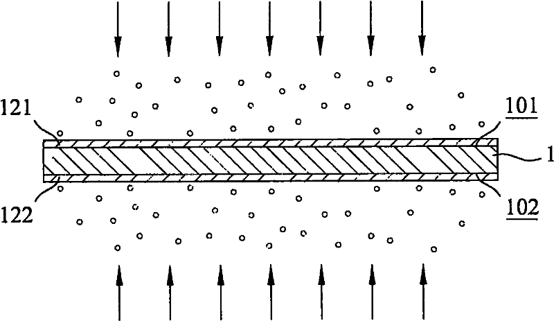
[0055] A first metal layer 121 and a second metal layer 122 are respectively formed on the top surface 101 and the bottom surface 102 of the substrate 1 by a vacuum coating method (step 102 ). The vacuum coating method in this step can include traditional vacuum sputtering, low-temperature vacuum sputtering, batch vacuum sputtering and c...

Embodiment 2

[0061] Embodiment 2: Aluminum substrate (1)

[0062] see image 3, is a flow block diagram showing the combination method of the substrate and the heat dissipation structure in this embodiment. and can also refer to Figure 4A ~ Figure 4F , is a diagram showing the various steps. The method of the present embodiment comprises the following steps:

[0063] A substrate 2 is provided (step 201). The substrate 2 in this embodiment is an aluminum substrate, because aluminum has high thermal conductivity and good heat dissipation, it can effectively export internal heat (see Figure 4A ).

[0064] A first metal layer 211 and a second metal layer 212 are respectively formed on the top surface 201 and the bottom surface 202 of the substrate 2 by vacuum coating (step 202 ). Same as the first embodiment, the vacuum coating method in this step can include traditional vacuum sputtering, low-temperature vacuum sputtering, batch vacuum sputtering and continuous vacuum sputtering, etc....

Embodiment 3

[0070] Embodiment 3: Aluminum substrate (2)

[0071] see Figure 5 , is a flow block diagram showing the combination method of the substrate and the heat dissipation structure in this embodiment. and can also refer to Figure 5 A~ Figure 5 F, is a schematic diagram showing the various steps. Since this embodiment is another embodiment using an aluminum substrate, the details of its implementation steps are mostly similar to those of the second embodiment, and the similarities will not be repeated, and only the key points will be described. The method of the present embodiment comprises the following steps:

[0072] A substrate 3 is provided (step 301). With embodiment 2, the substrate 3 in the present embodiment is an aluminum substrate (see Figure 5 A).

[0073] Form an insulating layer 322 at a predetermined position on the top surface 301 of the substrate 3 (step 302), see Figure 5 b.

[0074] Partially form a first metal layer 311 and a second metal layer 312 a...


PUM

PropertyMeasurementUnit
thicknessaaaaaaaaaa

Abstract

The invention discloses an improved combination structure and a combining method of a baseplate and a heat dissipating structure. The method comprises the following steps of: (a) providing the baseplate; (b) respectively forming a first metal layer and a second metal layer on the top surface and the bottom surface of the baseplate in a vacuum evaporation coating method; and (3) leading the heat dissipating structure to be combined on the second metal layer of the bottom surface of the baseplate by means of combination. According to the improved combination structure of the baseplate and the heat dissipating structure obtained by using the combining method, a heat source conductive interface of a ceramic baseplate or an aluminium baseplate can be converted into a metal interface with better heat transfer property through a high polymer adhesive by adopting a vacuum coating method, thereby the whole heat transfer coefficient is substantially increased, and the unweldable characteristic of the kind of baseplates is solved; and due to the increasing of thermal conductivity, the service life of the LED (Light-Emitting Diode) grain packaging is prolonged and the availability factor of the LED grain packaging is improved.

Description

technical field [0001] The invention relates to a combined application of a substrate and a heterogeneous element, in particular to an improved combination of a substrate and a heat dissipation structure and a method thereof. Background technique [0002] In recent years, the application territory of light-emitting diodes (LEDs) has continued to expand to the consumer market, and the application of white light lighting has also followed the issue of global warming, making LEDs continue to be popular after backlight applications. However, with the inevitable replacement trend of LED light sources, the problem of heat dissipation will officially become a key impact on LED development and product penetration; poor heat dissipation will cause several serious phenomena, first of all, it will cause wavelength changes, such as from 450nm The blue light becomes blue-green at 480nm, which will secondly reduce the brightness (the internal quantum conversion efficiency of the LED is re...

Claims


Application Information

Patent Timeline
Patent Type & Authority Applications(China)
IPC IPC(8): H01L33/00H01L21/50H01L33/48H01L33/64H01L23/12H01L23/36
Inventor 杨维钧吴煜明赵伟杰陈怡臻
Owner PARAGON TECH
Why Eureka
Try Eureka