
Rapid cooling device and temperature control method thereof

A fast heating and cooling technology, applied in the direction of temperature control, non-electric variable control, control/regulation system, etc., can solve the problem of SCR's large size, increased use of influence, AC and DC control signals and output power circuit noise interference, etc. problems, to achieve the effect of reducing volume, reducing noise and interference, and precise control of cavity heating

Active Publication Date: 2012-05-16
PREMTEK INT
View PDF6 Cites 2 Cited by
  • Summary
  • Abstract
  • Description
  • Claims
  • Application Information

AI Technical Summary

Problems solved by technology

[0002] Existing optoelectronic semiconductor rapid heating and cooling process equipment uses a switching capacitor relay (Switching Capacitor Relay, SCR) as a controller for output power modulation. Circuits are prone to various noises and interferences during use, and the degree of their influence will increase significantly with the number of uses
[0003] In addition, commercially available SCRs are bulky and need to be equipped with heat sinks. Therefore, power control is generally carried out in groups, that is, one SCR needs to control multiple groups of heating sources at the same time, which is not conducive to the trend and demand for individual control of heating sources for heating and cooling equipment in the future.
[0004] When this existing control method is applied to the rapid temperature rise and fall process equipment of optoelectronic semiconductors, there will be noise interference between the AC and DC control signals and the output power circuit
In addition, the partition control method has fewer parameters that can be adjusted. Although the difficulty of adjustment is reduced, it also relatively sacrifices the adjustability of some areas, so that the uniformity of the reaction chamber is relatively limited.

Method used


Image

  • Rapid cooling device and temperature control method thereof
  • Rapid cooling device and temperature control method thereof
  • Rapid cooling device and temperature control method thereof

Examples


Embodiment Construction

[0013] The implementation of the present invention will be described in more detail below in conjunction with the accompanying drawings, so that those skilled in the art can implement it after studying this specification.

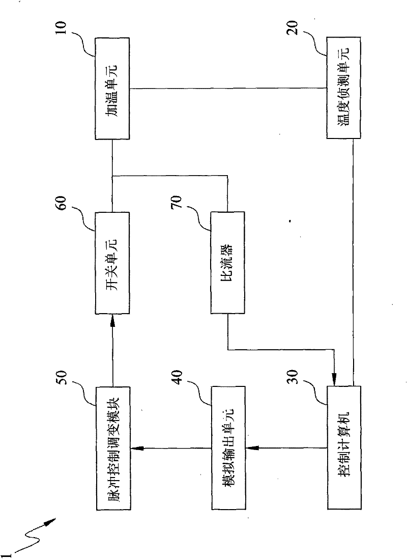
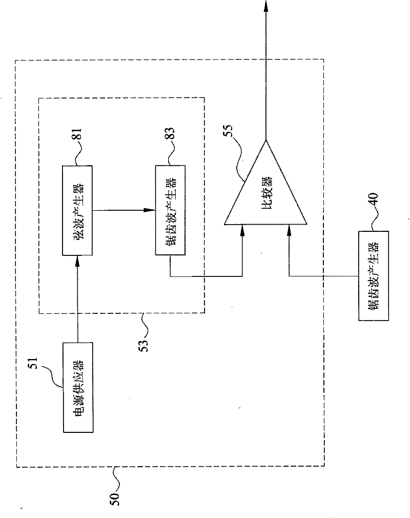
[0014] refer to figure 1 , is a schematic block diagram of the rapid heating and cooling device of the present invention. Such as figure 1 As shown, the rapid heating and cooling device 1 of the present invention includes a heating unit 10, a temperature detection unit 20, a control computer 30, an analog output unit 40, a pulse control modulation module 50, and a switch unit 60. The heating unit 10 includes a A cavity (not shown) containing an object to be heated and a plurality of heater arrays (not shown), the temperature detection unit 20 is connected to the heating unit 10 for measuring the temperature of the cavity in the heating unit 10 temperature, the control computer 30 is connected to the temperature detection unit 20, includes a temperature co...


PUM


Abstract

The invention discloses a rapid cooling device and a temperature control method thereof. The device comprises a heating unit, a temperature detection unit, a control computer, an analog output unit, a pulse control and modulation module and a switch unit. By using a pulse width modulation method, the existing electric heating adjuster is replaced by the pulse control and modulation module which is integrated with a power supplier, a waveform conversion circuit and a comparator, the total volume of a system is reduced, group control is not required, the noise and interference are reduced, the heating of a chamber can be controlled more accurately, and the process quality of various rapidly heated targets such as wafers, solar cells, photoelectric chips and the like can be promoted.

Description

technical field [0001] The invention relates to a rapid heating and cooling device and a temperature control method thereof, in particular, pulse width modulation (Pulse Width Modulation) is used to control the start and stop of heating. Background technique [0002] Existing optoelectronic semiconductor rapid heating and cooling process equipment uses a switching capacitor relay (Switching Capacitor Relay, SCR) as a controller for output power modulation. Circuits are prone to various noises and interferences during use, and the degree of their influence will increase significantly with the number of uses. [0003] In addition, commercially available SCRs are bulky and need to be equipped with heat sinks. Therefore, power control is generally performed in groups, that is, one SCR needs to control multiple sets of heating sources at the same time, which is not conducive to the trend and demand for individual control of heating sources for heating and cooling equipment in the...

Claims


Application Information

Patent Timeline
IPC IPC(8): G05D23/20
Inventor 林武郎吕学礼周明源石玉光萧文雄
Owner PREMTEK INT
Learn More