Dc-dc converter, module, power supply device and electronic apparatus
A DC-DC and converter technology, applied in the field of DC-DC converters, modules, power supply units and electronic equipment, can solve the problems of reverse voltage applied by diodes, difficult to suppress recovery current, and difficult to obtain results
- Summary
- Abstract
- Description
- Claims
- Application Information
AI Technical Summary
Problems solved by technology
Method used
Image

Examples
Embodiment approach 1
[0036] Hereinafter, the embodiments will be specifically described with reference to the drawings. The DC-DC converter according to the present application is used for a switching power supply or the like that converts a DC input voltage into a power supply voltage when supplying a power supply voltage to an information device or the like. The switching power supply is used as a power source for supplying DC power to electronic devices such as computers. In addition, it is also used as a variable power supply for supplying illuminating lights, audio equipment, microwave ovens, and the like with adjusted power supplies. The switching power supply is also used as a power source for supplying driving power to motors built in washing machines, refrigerators, and air conditioners. The switching power supply is not limited to the case of supplying small power, and can also be used as a power supply for supplying large power to drive motors of vehicles and trams.
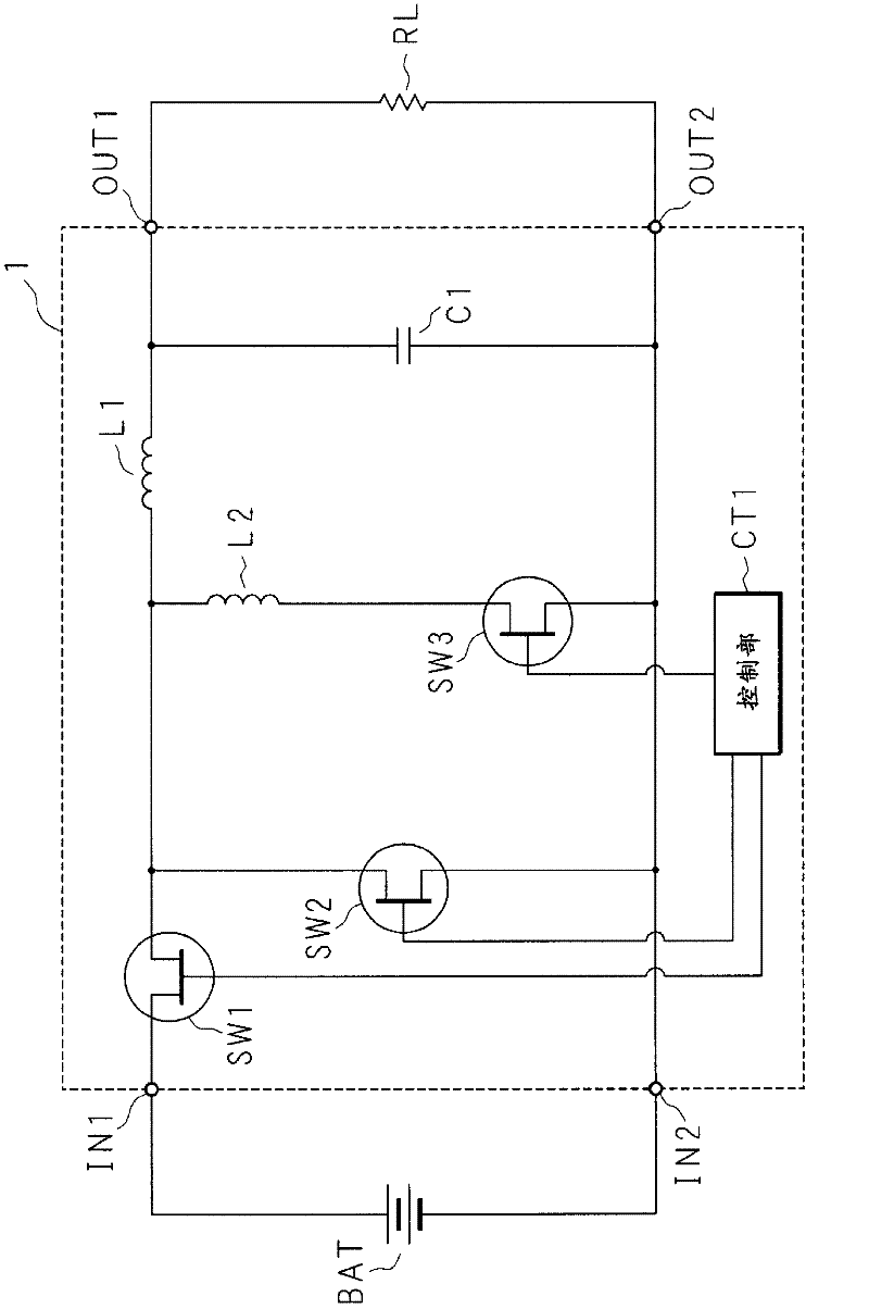
[0037] figure 1 It...
Embodiment approach 2
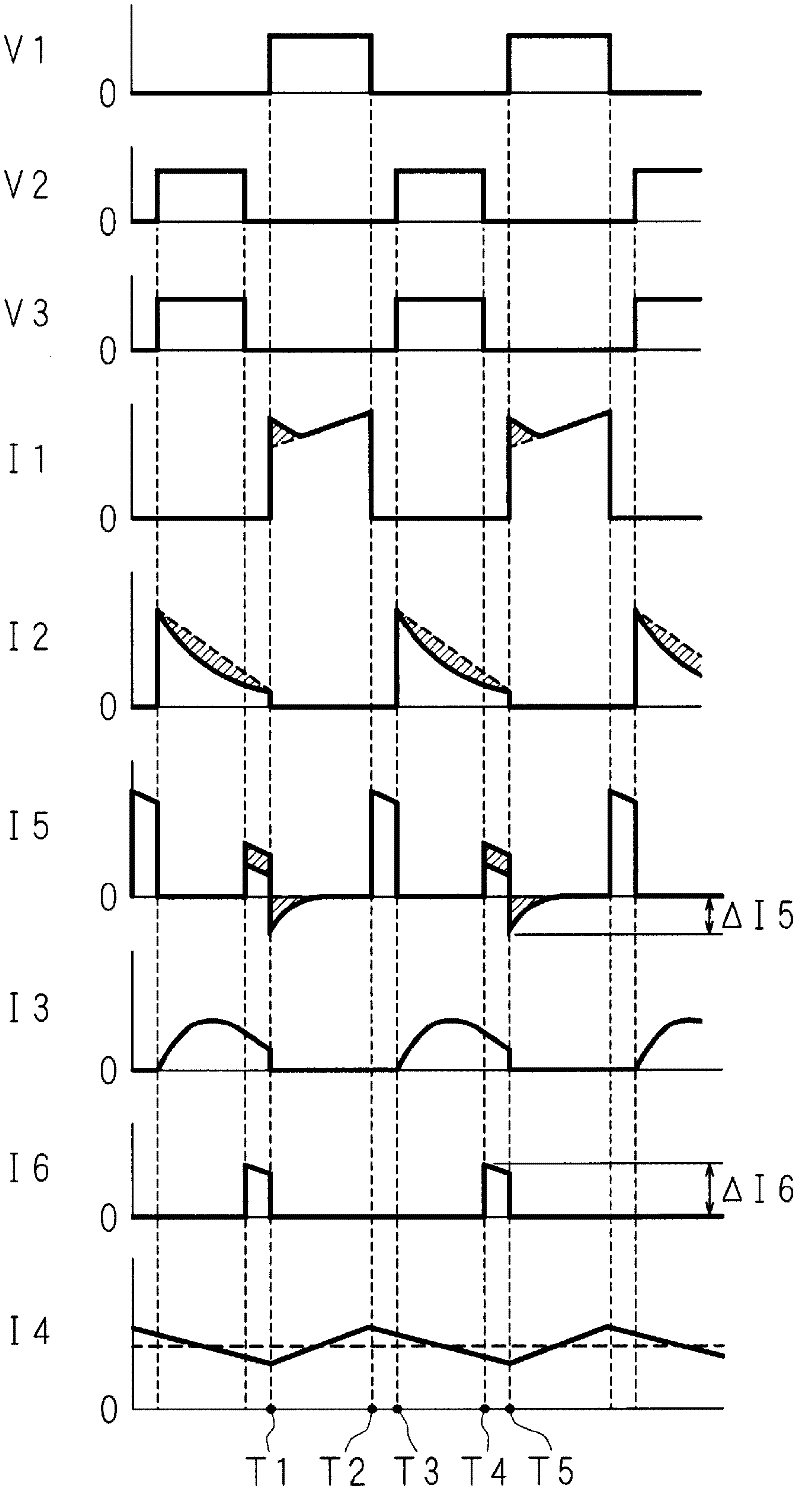
[0058] Figure 5 It is a time chart for explaining the operation of the DC-DC converter 1. The horizontal axis and the vertical axis of each graph represent time and voltage value or current value, respectively. In contrast to the first embodiment, the second switch SW2 and the third switch SW3 are turned on almost simultaneously. In the second embodiment, they are turned on at a predetermined time shift. The control unit CT1 turns on the third switch SW3 after turning on the first switch SW1 and before turning on the second switch SW2. Then, the control unit CT1 turns off the third switch SW3 after the second switch SW2 is turned off and before the first switch SW1 is turned on.
[0059] At the time T1 when the first switch is turned on, the current I1 flows through the first switch SW1, energy is accumulated in the first inductor L1, and the current I1 gradually increases with time. At time T2, the first switch SW1 is turned off, and the current I1 immediately becomes zero. ...
Embodiment approach 3
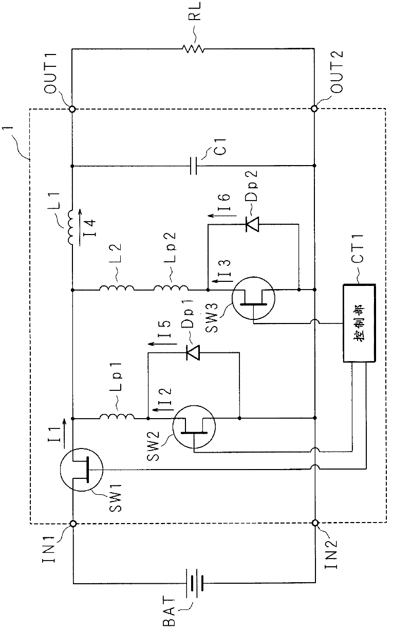
[0065] Image 6 It is a circuit diagram showing the module. In the third embodiment, a part of the circuit of the first embodiment is modularized. The module has a second switch SW2, a third switch SW3, and a second inductor L2. The source of the second switch SW2 is connected to the terminal A, and is connected to the source of the third switch SW3 via the second inductor L2. The drains of the second switch SW2 and the third switch SW3 are connected to the terminal B. The gates of the second switch SW2 and the third switch SW3 are connected to the terminal C and the terminal D, respectively. By replacing the second switch of the conventional synchronous rectification DC-DC converter with a module, the DC-DC converter 1 can be easily manufactured. In addition, by replacing the second switch of the DC-DC converter of the conventional synchronous rectification method with a module, it can be easily changed to the DC-DC converter 1 of the first and second embodiments.
[0066] ...
PUM
 Abstract
Description
Claims
Application Information
 - R&D
- Intellectual Property
- Life Sciences
- Materials
- Tech Scout
- Unparalleled Data Quality
- Higher Quality Content
- 60% Fewer Hallucinations
Browse by: Latest US Patents, China's latest patents, Technical Efficacy Thesaurus, Application Domain, Technology Topic, Popular Technical Reports.
© 2025 PatSnap. All rights reserved.Legal|Privacy policy|Modern Slavery Act Transparency Statement|Sitemap|About US| Contact US: help@patsnap.com