
Processing method of inferior residuum

A processing method and residual oil technology, which are applied in the petroleum industry, hydrotreating process, and hydrocarbon oil treatment, etc., can solve the problems of shortened operation period of UFR reactor and low volume of hydrogen oil, so as to avoid the decrease of hydrogenation catalyst activity, The effect of slowing down the rate of ascent and slowing down the rate of inactivation

Active Publication Date: 2012-05-23
CHINA PETROLEUM & CHEM CORP +1
View PDF5 Cites 12 Cited by
  • Summary
  • Abstract
  • Description
  • Claims
  • Application Information

AI Technical Summary

Problems solved by technology

Although this method can process residual oil with high sulfur content and high metal content, the volume of hydrogen oil in the UFR reactor is relatively low due to its own characteristics, so that the catalyst in the UFR reactor is in a relatively hydrogen-deficient environment. Practice shows that CN101519603A The technical route has a significant impact on the stable operation of the UFR reactor, mainly manifested in the significantly shortened operating cycle of the UFR reactor

Method used


Image

  • Processing method of inferior residuum
  • Processing method of inferior residuum
  • Processing method of inferior residuum

Examples


Embodiment 1

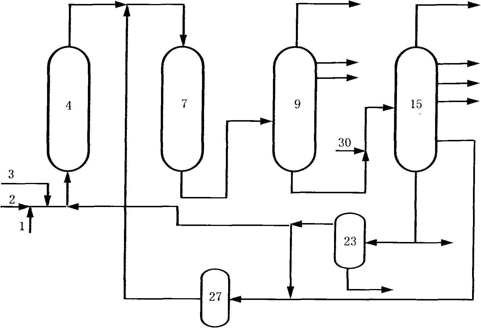
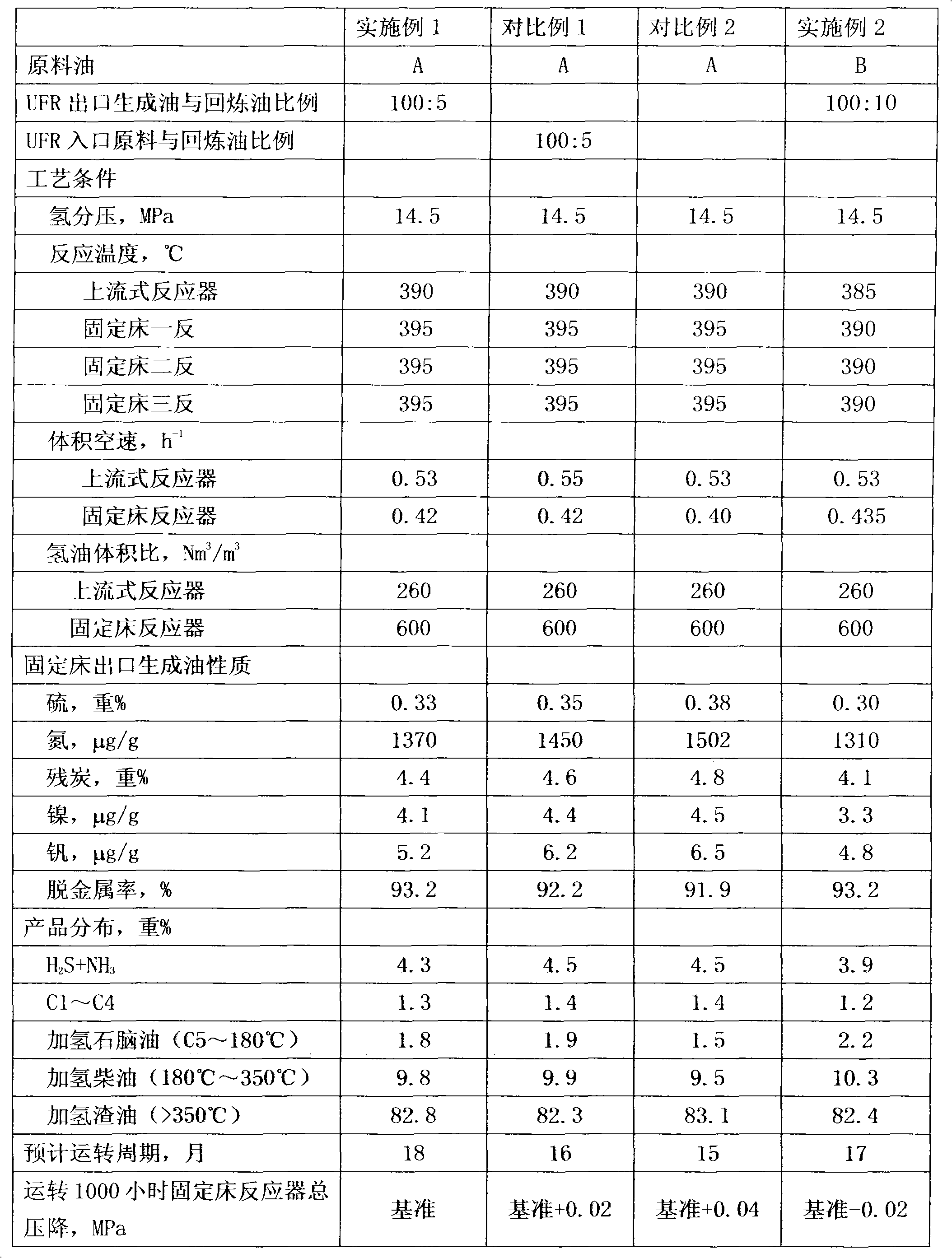
[0053] The residual oil hydrogenation unit of embodiment 1 comprises four reactors, an upflow reactor (UFR) and three fixed bed (trickle bed) reactors, and the upflow reactor catalyst FZC-10UH is filled in the upflow reactor , the first fixed bed reactor (referred to as the first fixed bed reactor) is filled with the protective agent FZC-103 and the demetallization catalyst FZC-28, and the second fixed bed reactor (referred to as the fixed bed second reactor) is filled with the desulfurization catalyst FZC-34A, The third fixed bed reactor (fixed bed three reactors for short) is filled with denitrification catalyst FZC-41A. Wherein, the loading ratio (volume) of upflow reactor catalyst: protective agent: demetallization catalyst: desulfurization catalyst: denitrogenation catalyst is 42:1:12:30:15, that is, the ratio of upflow reactor catalyst to fixed bed reactor catalyst The filling ratio is 42:58.

[0054] The raw material A used in Example 1 is a mixture of vacuum residue, ...

Embodiment 2

[0063] The residual oil hydrogenation unit of embodiment 2 comprises four reactors, an upflow reactor and three fixed bed reactors, the upflow reactor catalyst FZC-10UH is filled in the upflow reactor, and the fixed bed one reversely fills the protective agent FZC-103 and demetallization catalyst FZC-28, fixed-bed two-reverse packing desulfurization catalyst FZC-34A, fixed-bed three-reverse packing denitrogenation catalyst FZC-41A. Wherein the loading ratio of upflow reactor catalyst: protective agent: demetallization catalyst: desulfurization catalyst: denitrogenation catalyst is 34:0.5:9.5:36:20, that is, the loading ratio of upflow reactor catalyst to fixed bed reactor catalyst is 34:66.

[0064] The raw material B used in Example 2 is a mixture of vacuum residue, vacuum gas oil and catalytic cracking slurry distillate, and the mass ratio of the three mixtures is 75:15:10, and its properties are shown in Table 1. The raw material oil B is mixed with hydrogen and enters the...


PUM


Abstract

The invention discloses a processing method of an inferior residuum. The method comprises steps that: residuum and any heavy distillate oil are subject to an up-flow hydrogenation reaction; a reaction effluent is mixed with catalytic cracking cycle oil, and the mixture is subject to a trickle bed hydrogenation reaction; a reaction product is separated, such that gas, hydrogenated naphtha, hydrogenated diesel oil and hydrogenated residuum are obtained; the hydrogenated residuum is subject to a catalytic cracking reaction with any vacuum gas oil; a catalytic cracking reaction product is separated, such that gasoline, diesel oil, catalytic cracking cycle oil and catalytic cracking oil slurry are obtained; the catalytic cracking cycle oil is recycled and delivered to the inlet of a trickle bed reactor. Compared to prior art, with the method provided by the invention, residuum hydrogenation treatment and catalytic cracking can be more effectively combined, and an implementation effect is better. Also, the operation period of the reaction apparatus can be prolonged.

Description

technical field [0001] The invention relates to a processing method for lightening residual oil, more specifically, a method for treating residual oil raw materials with high sulfur and high metal content by combining two processes of residual oil hydrotreating and catalytic cracking. technical background [0002] With the development of the economy, the demand for light oil is increasing day by day, but the demand for heavy fuel oil is gradually decreasing. At the same time, the trend of crude oil becoming heavier and worse is becoming more and more obvious. One of the main goals pursued. [0003] Among the various processes for lightening residual oil, it is a better process to firstly carry out hydrogenation treatment on the residual oil, and then carry out catalytic cracking processing on the hydrogenated tail oil. The residual oil is hydrotreated to remove impurities such as metals, sulfur, nitrogen, etc., and the hydrogen content is increased. It can be used as a high...

Claims


Application Information

Patent Timeline
IPC IPC(8): C10G69/00
Inventor 吴锐翁延博耿新国刘铁斌李洪广张庆军关明华
Owner CHINA PETROLEUM & CHEM CORP
Learn More