
Glass paste for forming a photosensitive sealing layer, plasma display manufacturing method using the same, and plasma display

A technology of glass paste and plasma, which is applied in the manufacture of discharge tubes/lamps, exhaust sealing, cold cathode manufacturing, etc., and can solve the problems of forming with good precision without disclosure

Inactive Publication Date: 2012-05-23
TORAY IND INC
View PDF7 Cites 1 Cited by
  • Summary
  • Abstract
  • Description
  • Claims
  • Application Information

AI Technical Summary

Problems solved by technology

Although the barrier rib height adjustment layer described in this document is effective for the above-mentioned problems, it does not disclose a method of forming it on the top of a large-scale and large-area barrier rib with good precision. Under the condition of advanced technology, it is difficult to accurately form the partition height adjustment layer described in Patent Document 2 on the top of the partition wall.

Method used


Image

  • Glass paste for forming a photosensitive sealing layer, plasma display manufacturing method using the same, and plasma display
  • Glass paste for forming a photosensitive sealing layer, plasma display manufacturing method using the same, and plasma display
  • Glass paste for forming a photosensitive sealing layer, plasma display manufacturing method using the same, and plasma display

Examples


Embodiment 1~14

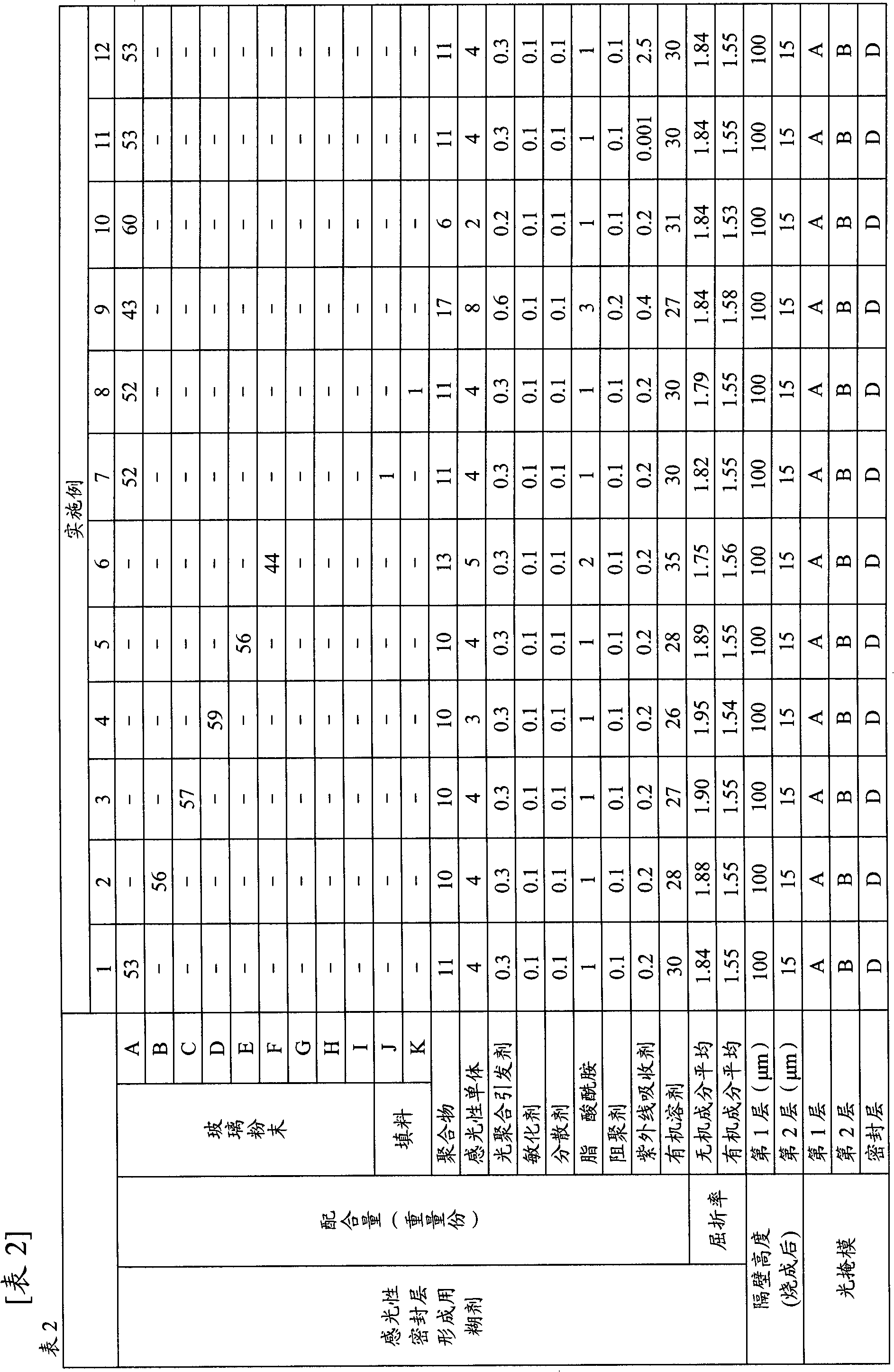
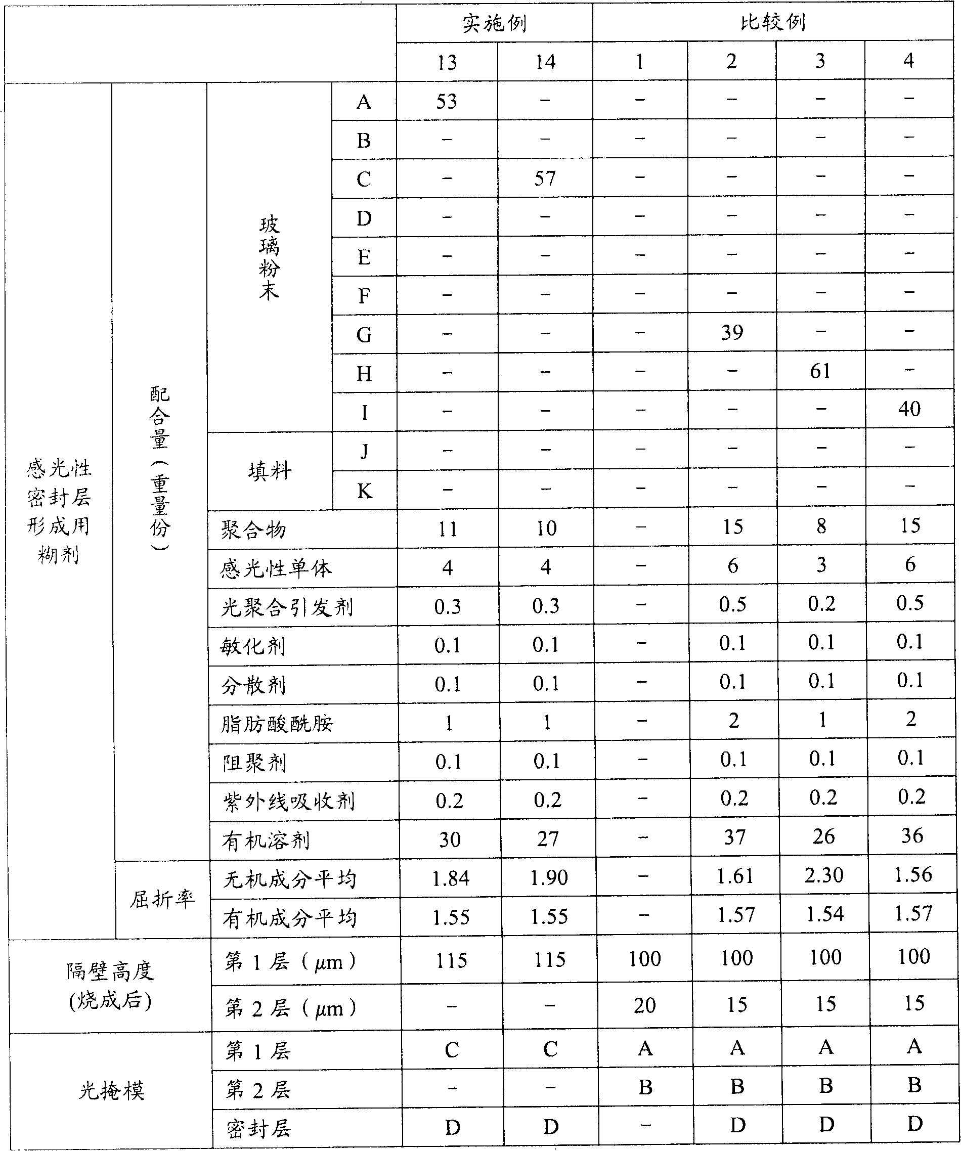
[0106] (Examples 1-14, Comparative Examples 1-4)

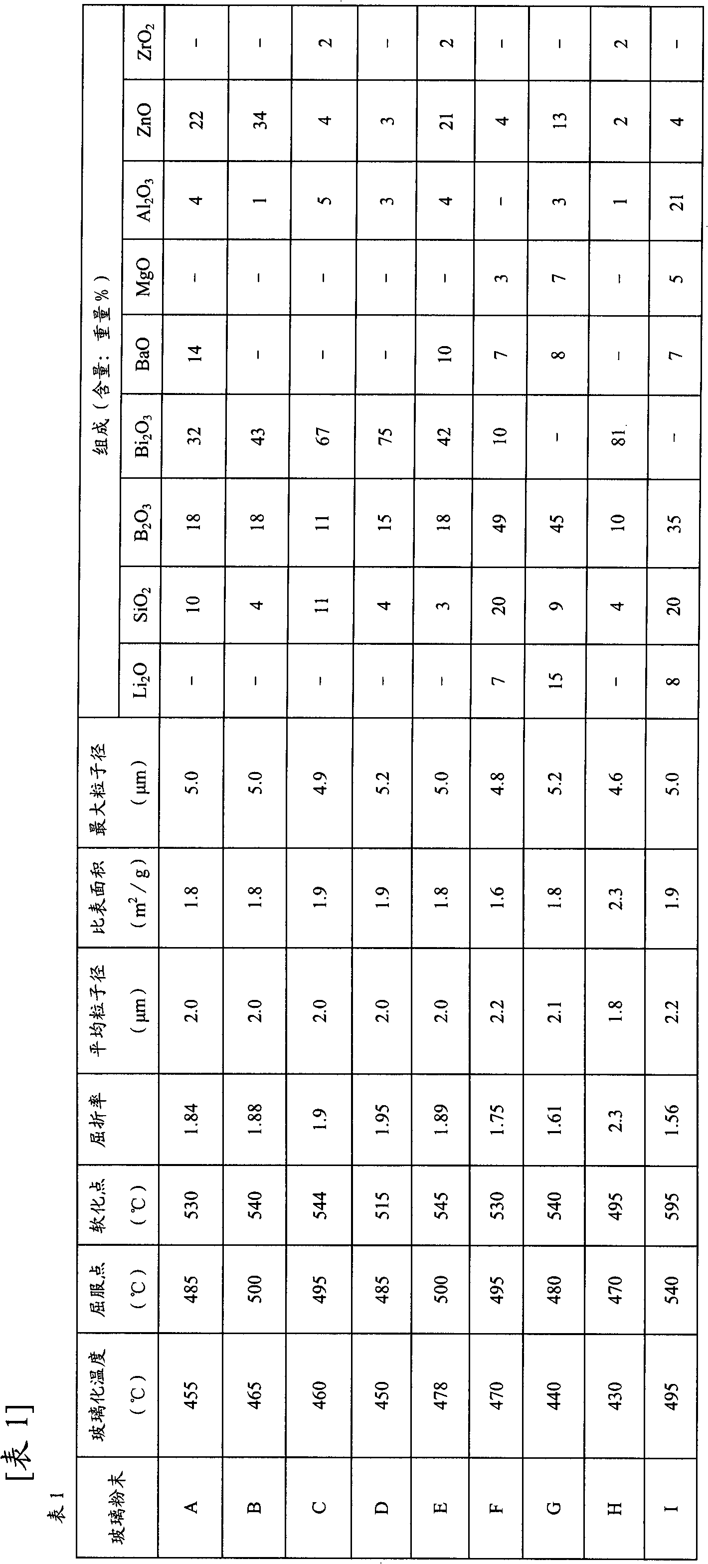
[0107] Table 1 shows the glass powders used in Examples.

[0108]

[0109] In addition, the average particle diameter (D50) and maximum particle diameter (Dmax) of the following glass powder and a filler are the values ​​measured using the Nikkiso Co., Ltd. microtrack particle size distribution analyzer (MT3000). In addition, the glass transition temperature and softening point of the glass powder are the following values: Using the differential thermal analysis method, heating in the air at a heating rate of 10°C / min, the horizontal axis represents the temperature, and the vertical axis represents the heat, and the value read by drawing the DTA curve . The yield point of the glass powder is a value measured by heating in air at a temperature increase rate of 5° C. / min using a thermal dilatometer.

[0110] In addition, the refractive index measurement of a glass powder and a filler was performed using the Becke method, an...


PUM


Abstract

Disclosed is a photosensitive paste including (A) a glass powder with a glass transition point of 410-480 DEG C, a yield point of 470-510 DEG C, and a softening point of 515-550 DEG C; (B) a photosensitive organic component; (C) a UV absorber; and (D) a solvent. The glass paste for forming a photosensitive sealing layer is characterized in that the inorganic component including the glass powder has an average refractive index (N1) fulfilling equation (1): 1.75<=N1<=1.95. Thus, crosstalk and noise can be prevented, and a low energy consumption plasma display can be obtained.

Description

technical field [0001] The present invention relates to a glass paste for forming a photosensitive sealing layer and a method for producing a plasma display. Background technique [0002] Compared with liquid crystal panels, plasma display panels (PDPs) can display at a higher speed and are easier to increase in size, so they have been applied to fields such as OA equipment and advertising display devices. In addition, it is effectively used in the high-quality television field and the like. [0003] The small gap formed between the two glass substrates of the front panel and the rear panel of the PDP is used as a discharge space, so that plasma discharge occurs between the anode and cathode electrodes, and the phosphors installed in the discharge space are irradiated by the gas sealed in the discharge space. The ultraviolet light makes it emit light, thereby displaying. In this case, the electrodes are respectively arranged in strips on the front panel and the rear panel,...

Claims


Application Information

Patent Timeline
IPC IPC(8): C03C8/24H01J9/02H01J9/26H01J11/34H01J17/18H01J17/49
CPCC03C8/14H01J9/261C03C8/16H01J11/48C03C8/04C03C8/24H01J9/02H01J9/26
Inventor 田中明彦井户英夫
Owner TORAY IND INC
Features
  • Generate Ideas
  • Intellectual Property
  • Life Sciences
  • Materials
  • Tech Scout
  • Unparalleled Data Quality
  • Higher Quality Content
  • 60% Fewer Hallucinations
Learn More