Plasma cleaning device

A technology of plasma cleaning and plasma cavity, which is applied in the field of ion surface treatment devices and its control, can solve the problems of affecting the electrical properties of the surface medium, the easy loss of the surface medium, the density of the ion beam, and the high bombardment intensity, etc., so as to avoid the surface properties of the medium Effect of drift or thickness loss, precise control of ion bombardment intensity

Active Publication Date: 2012-06-06
SEMICONDUCTOR MANUFACTURING INTERNATIONAL (BEIJING) CORP
View PDF5 Cites 14 Cited by
  • Summary
  • Abstract
  • Description
  • Claims
  • Application Information

AI Technical Summary

Problems solved by technology

[0004] The existing technology has the following problems: because the plasma is full of the plasma chamber, the density and bombardment intensity of the ion beam are both large after the accelerating electric field is accelerated; during the cleaning process, the thickness of the surface medium is prone to loss, and at the same time Affects the electrical properties of the surface medium
If the dielectric constant increases, the parasitic capacitance between the dielectric layer and other metal layers will change, which will increase the RC delay and even affect the operation of the device

Method used


Image

  • Plasma cleaning device
  • Plasma cleaning device
  • Plasma cleaning device

Examples


no. 1 example

[0042] This embodiment adopts an integrated plasma chamber. In the plasma chamber, the deflecting electric field overlaps with the accelerating electric field. When the ions pass through the electric field filter, they are still accelerated by the accelerating electric field.

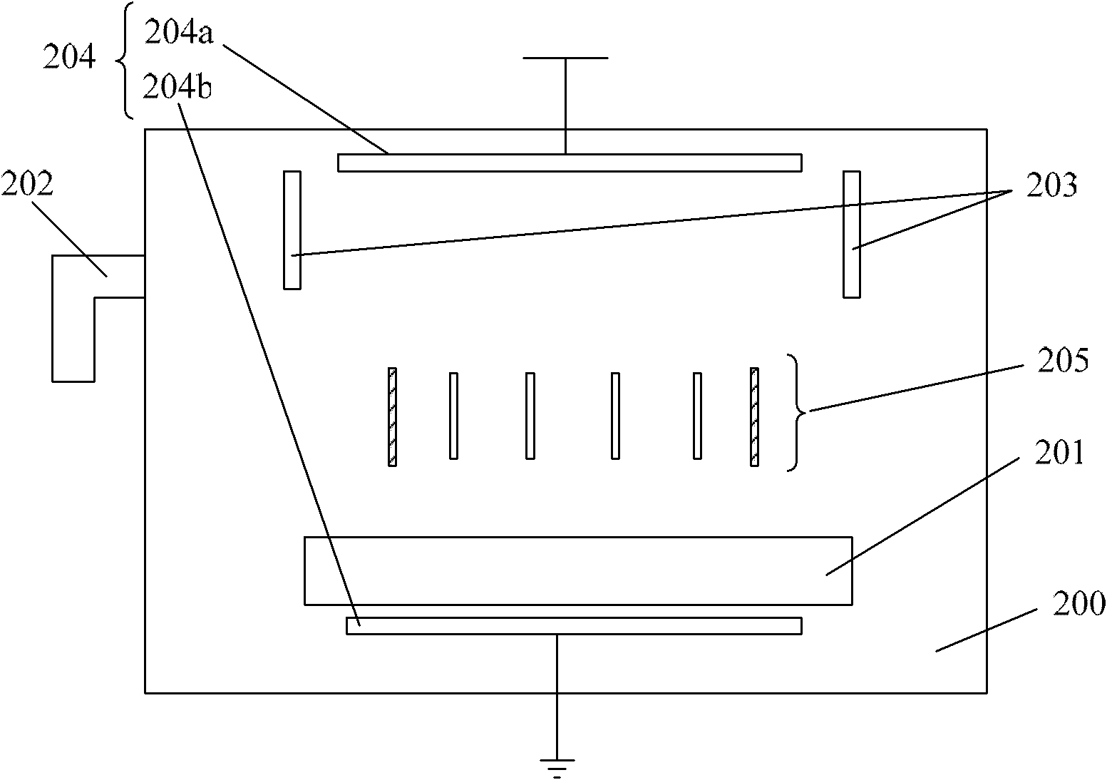
[0043] like image 3 As shown, the plasma cleaning device described in this embodiment includes:

[0044] The plasma chamber 200 is arranged on the base 201 at the bottom of the plasma chamber 200;

[0045] A vent pipe 202 connected to the plasma chamber 200 is used to introduce a cleaning gas as a plasma source into the plasma chamber 200;

[0046] Plasma generator 203, the plasma generator 203 can be inductively coupled plasma (ICP), and the cleaning gas in the plasma chamber 200 is ionized by passing high-frequency radio frequency signals to the electrodes arranged around the chamber , forming plasma;

[0047] Ion accelerator 204, described ion accelerator 204 comprises the upper electrode plate 2...

no. 2 example

[0061] In the foregoing embodiments, the structure of the device is relatively simple, and the accelerating electric field and the deflecting electric field overlap. Although the uniform electric field is taken as an ideal model, the electric field in the integrated plasma chamber is actually more complicated. The difference in electric field and plasma density in different regions will easily affect the uniformity of ions bombarded on the surface of the workpiece. This embodiment also provides a plasma cleaning device using a biased plasma source, so that the deflection electric field and the acceleration electric field are isolated without affecting each other.

[0062] like Image 6 As shown, the difference between the plasma cleaning device described in this embodiment and the first embodiment is:

[0063] The plasma generator 203 and the ion accelerator 204 are all biased at the top of the plasma chamber, wherein the ion accelerator 204 can be an electromagnetic coil acc...

no. 3 example

[0083] This embodiment adopts an integrated plasma chamber. In the plasma cavity, the deflection magnetic field overlaps with the accelerating electric field. When the ions pass through the magnetic field filter, they are still accelerated by the accelerating electric field.

[0084] like Figure 10 As shown, the plasma cleaning device described in this embodiment includes:

[0085] The plasma chamber 400 is set on the base 401 at the bottom of the plasma chamber 400;

[0086] A vent pipe 402 connected to the plasma chamber 400 is used to introduce cleaning gas as a plasma source into the plasma chamber 400;

[0087] Plasma generator 403, the plasma generator 403 can be an inductively coupled plasma generator (ICP), by passing high-frequency radio frequency signals to the electrodes arranged around the chamber, the cleaning gas in the plasma chamber 400 Ionize to form plasma;

[0088] Ion accelerator 404, described ion accelerator 404 comprises the upper electrode plate 4...


PUM


Abstract

The invention provides a plasma cleaning device which comprises a plasma chamber, a base, a plasma generator, an ion accelerator and a filter, wherein the base is arranged in the plasma chamber and used for bearing a workpiece to be cleaned, the plasma generator is used for generating plasmas, the ion accelerator is used for generating an accelerating field for accelerating ions in the plasmas to form an ion beam, the filter is arranged on the path of the ion beam and is used for deflecting the movement direction of ions in the ion beam through a deflection field and filtering ions shot to the workpiece to be cleaned so as to reduce throughput of ions in the ion beam and further accurately control the intensity of ion bombardment; therefore dielectric surface property shifting or thickness loss caused by excessive ion beam bombardment can be avoided.

Description

technical field [0001] The invention relates to the technical field of semiconductors, in particular to a plasma surface treatment device and a control method thereof. Background technique [0002] In the semiconductor manufacturing process, the method of plasma cleaning is used to pre-clean the surface of the semiconductor structure on the wafer (Re-active Pre-Clean, RPC), which has been widely used in metal interconnection, dielectric deposition, surface planarization and other processes middle. Plasma cleaning mainly uses the physical bombardment effect of plasma to remove the natural oxide layer on the surface of the semiconductor structure, the residues of the previous process, and other impurities and defects in a process similar to etching. It has the characteristics of fast cleaning speed and strong cleaning adaptability. More information about the plasma cleaning process can be found in the Chinese patent application No. 200880009987.6. [0003] Existing plasma c...

Claims


Application Information

Patent Timeline
Patent Type & Authority Applications(China)
IPC IPC(8): H01J37/32B08B7/00H01L21/00
Inventor 何伟业
Owner SEMICONDUCTOR MANUFACTURING INTERNATIONAL (BEIJING) CORP
Why Eureka
Try Eureka