
Energy-saving device and method for polycrystalline silicon reduction furnace with polycrystalline silicon insert heat insulation layer

An energy-saving device, polysilicon technology, applied in the direction of silicon, sustainable manufacturing/processing, climate sustainability, etc., can solve the problems of thinning furnace body, poor mirror effect, reducing radiation heat transfer, etc., to reduce energy consumption loss , Easy to disassemble and replace, reduce the effect of radiant heat

Inactive Publication Date: 2014-02-12
TIANJIN UNIV
View PDF5 Cites 0 Cited by
  • Summary
  • Abstract
  • Description
  • Claims
  • Application Information

AI Technical Summary

Problems solved by technology

Since a large amount of heat taken away by the cooling medium comes from the energized silicon rods, which causes energy loss in the reduction furnace, many manufacturers use inner wall polishing to reduce radiation heat transfer, hoping to reduce energy loss inside the furnace body to achieve energy saving.
Because the chemical reaction in the reduction furnace will produce hydrogen chloride and high-chlorine silane products, and at the same time, amorphous silicon will be deposited on the inner wall of the furnace, which will reduce the mirror effect of the polished surface of the inner wall of the furnace and reduce the reflection of the inner wall on the silicon rod radiation. Therefore, it is necessary to regularly polish and maintain the wall surface of the furnace body, but it is difficult to directly polish the wall surface of the furnace body, and the mirror effect of polishing is poor, which causes the thickness of the furnace body to decrease and is not conducive to safe production. For this reason we propose a polysilicon reduction furnace energy-saving method and implementation device equipped with a polysilicon insert interlayer to prevent the deposition of amorphous silicon on the inner wall of the furnace and avoid the contact of high chlorosilane and hydrogen chloride gas with the inner wall of the furnace, thereby Further reduction of energy loss in the reduction furnace

Method used


Image

  • Energy-saving device and method for polycrystalline silicon reduction furnace with polycrystalline silicon insert heat insulation layer
  • Energy-saving device and method for polycrystalline silicon reduction furnace with polycrystalline silicon insert heat insulation layer
  • Energy-saving device and method for polycrystalline silicon reduction furnace with polycrystalline silicon insert heat insulation layer

Examples


Embodiment approach 1

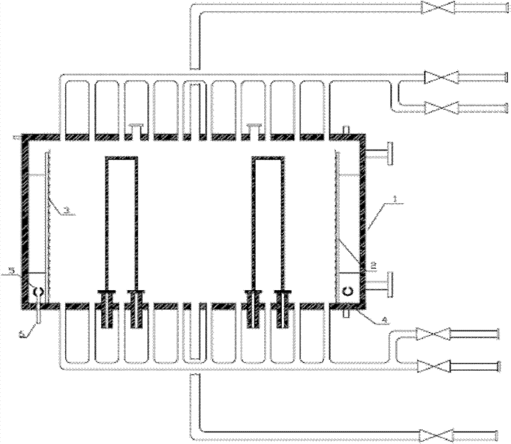
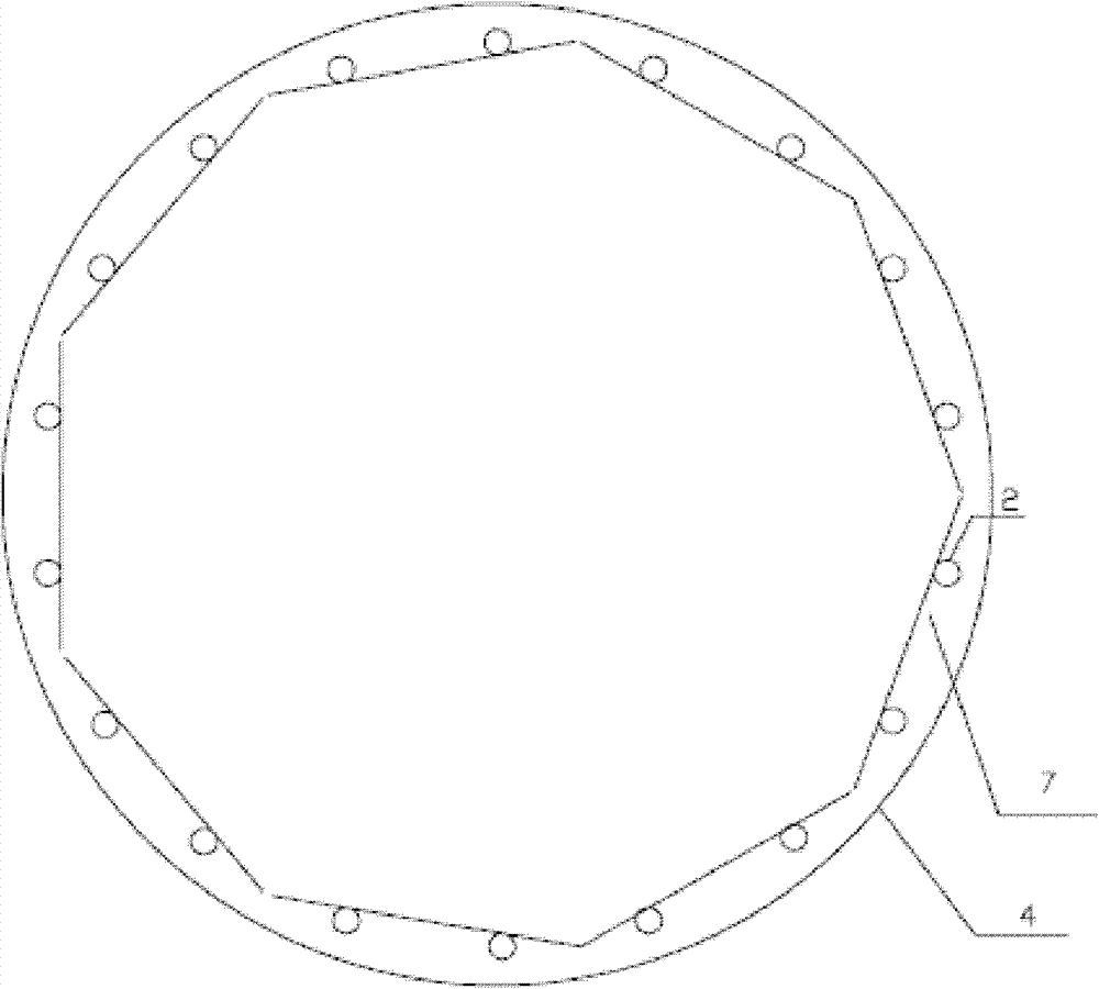
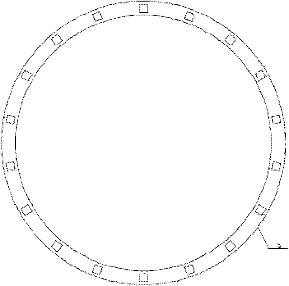
[0024] Implementation mode 1: if figure 1 , 2 As shown, the polysilicon reduction furnace includes: 1- double-layer furnace body with jacketed cooling water device, 2- stainless steel tube, 3- stainless steel plate with grooves, 4- reduction furnace chassis, 5- ring inlet pipe, 6 -Chassis air intake, 7-polysilicon inserts, 8-bolts. Among them, the double-layer furnace body (1) containing the jacket cooling water device is fixed on the reduction furnace chassis (4), and the stainless steel pipe (2) is connected with the furnace body (1) through bolts (8), as image 3 , 4 As shown, the column frame is made of stainless steel. The stainless steel tube is a square tube with a side length of 30mm and a width of the stainless steel plate of 40mm. The stainless steel tube (2) and the stainless steel plate (3) with grooves are connected by welding. The interval of the grooves on the stainless steel plate is 100mm and the depth is 50mm, the width of the groove is 0.25mm, the angle ...

Embodiment approach 2

[0028] Implementation mode 2: if figure 1 , 2 As shown, the polysilicon reduction furnace includes: 1- double-layer furnace body with jacketed cooling water device, 2- stainless steel tube, 3- stainless steel plate with grooves, 4- reduction furnace chassis, 5- ring inlet pipe, 6 -Chassis air intake, 7-polysilicon inserts, 8-bolts. Wherein, the double-layer furnace body (1) containing the jacket cooling water device is fixed on the reduction furnace chassis (4), the stainless steel pipe (2) is connected with the furnace body (1) by bolts (8), and the stainless steel pipe (2) and A thermal insulation layer composed of polysilicon inserts (7), such as image 3 , 4 As shown, the frame is made of stainless steel. The stainless steel tube is a square tube with a side length of 30mm and a width of the stainless steel plate of 40mm. The stainless steel tube (2) and the stainless steel plate (3) with grooves are connected by welding. The interval of the grooves on the stainless st...

Embodiment approach 3

[0033] Implementation mode 3: if figure 1 , 2 As shown, the polysilicon reduction furnace includes: 1- double-layer furnace body with jacketed cooling water device, 2- stainless steel tube, 3- stainless steel plate with grooves, 4- reduction furnace chassis, 5- ring inlet pipe, 6 -Chassis air intake, 7-polysilicon inserts, 8-bolts. Among them, the double-layer furnace body (1) containing the jacket cooling water device is fixed on the reduction furnace chassis (4), the column frame (2) and the furnace body (1) are connected by bolts (8), and the stainless steel pipe (2) and polysilicon insert (7) composed of heat insulation layer, such as image 3 , 4 As shown, the frame is made of stainless steel. The stainless steel tube is a square tube with a side length of 40mm and a width of the stainless steel plate of 60mm. The stainless steel tube (2) and the stainless steel plate (3) with grooves are connected by welding. The interval of the grooves on the stainless steel plate i...


PUM

PropertyMeasurementUnit
diameteraaaaaaaaaa
depthaaaaaaaaaa
widthaaaaaaaaaa

Abstract

The invention belongs to an energy-saving device and an energy-saving method for a polycrystalline silicon reduction furnace with a polycrystalline silicon insert heat insulation layer. A distance between a heat insulation layer consisting of stainless steel tubes and polycrystalline silicon inserts and an inner wall of a furnace body is 25 to 250mm; the heat insulation layer is connected with the inner wall of the furnace body, and the furnace body is fixed on a base through a flange; a base plate air inlet is formed in the base, hydrogen or hydrogen silicon tetrachloride gas enters an annular air inlet tube through the base plate air inlet, a square opening is formed in the annular air inlet tube, and the hydrogen or hydrogen silicon tetrachloride gas enters a gap between the furnace body and the heat insulation layer through the annular air inlet tube, and is filled in the gap; by adopting the heat insulation layer consisting of a stainless steel tube cylindrical frame and the polycrystalline silicon inserts, radiant heat-transfer loss of silicon rods in the furnace to a wall surface of the furnace body is reduced, and high-purity polycrystalline silicon products are deposited on the polycrystalline silicon inserts on the heat insulation layer; the polycrystalline silicon inserts on the heat insulation layer are not polluted by metals in the process of growing the polycrystalline silicon by employing a frame cooling system; and due to the adoption of a wall surface protection system, a mirror surface on the inner wall of the furnace body is not polluted.

Description

technical field [0001] The invention belongs to the technical field of polysilicon production, in particular to an energy-saving method and device for a polysilicon reduction furnace for producing polysilicon by the Siemens method, including the energy-saving device and method for a polysilicon reduction furnace equipped with a polysilicon insert heat insulating layer. Background technique [0002] Polysilicon is widely used in the fields of electronics and solar energy. At present, polysilicon manufacturers at home and abroad mainly use the "improved Siemens method". The production process of this method is to use chlorine and hydrogen to synthesize hydrogen chloride (or purchased hydrogen chloride), hydrogen chloride and silicon powder to synthesize trichlorosilane at a certain temperature, and then carry out rectification, separation and purification of trichlorosilane, and the purified high-purity After trichlorosilane and hydrogen are mixed in proportion, they are passe...

Claims


Application Information

Patent Timeline
Patent Type & Authority Patents(China)
IPC IPC(8): C01B33/03
CPCY02P20/10
Inventor 刘春江段连黄哲庆郄思远周阳
Owner TIANJIN UNIV
Learn More