Double work-piece stage exchanging device based on single/double drive stepping scanning, and method thereof

A step-and-scan, double-workpiece technology, applied in photoplate-making process exposure devices, semiconductor/solid-state device manufacturing, electrical components, etc., can solve the problems of large reaction force of the base, increase the time for changing the stage, and affect the dynamic performance of the system. , to achieve the effect of fast driving speed, small mass and inertia

Inactive Publication Date: 2012-06-13
HARBIN INST OF TECH
View PDF10 Cites 2 Cited by
  • Summary
  • Abstract
  • Description
  • Claims
  • Application Information

AI Technical Summary

Problems solved by technology

In the patent CN101201555, the conveyor belt and the docking slider are used to complete the stage changing process, the movement rhythm is small, and the operation and maintenance are simple. However, the conveyor belt mechanism and the docking slider are fixed on the abutment, so there will be a large force during the stage changing process On the abutment, it has a great influence on the overall dynamic performance
In the patent CN1485694, the table-changing operation is completed by the docking of the Y-direction linear motor and the linear guide rail. However, due to the excessive gap in the middle of the abutment, a bridging device is introduced, which increases the movement rhythm and increases the time for table-changing. At the same time, the X-direction linear motor magnetically The steel part is fixed on the abutment, and the movement of the moving parts will generate a large reaction force on the abutment when the platform is changed, which in turn affects the dynamic performance of the entire system
In the patent CN101770181, the docking of the replacement unit is used to complete the work of changing the platform, but the guide device is fixed on the abutment. During the movement of changing the platform, the moving parts will generate a large reaction force on the abutment, which in turn affects the dynamic performance of the entire system.
Therefore, the current dual-platform solution needs to be improved.

Method used


Image

  • Double work-piece stage exchanging device based on single/double drive stepping scanning, and method thereof
  • Double work-piece stage exchanging device based on single/double drive stepping scanning, and method thereof
  • Double work-piece stage exchanging device based on single/double drive stepping scanning, and method thereof

Examples


Embodiment 1

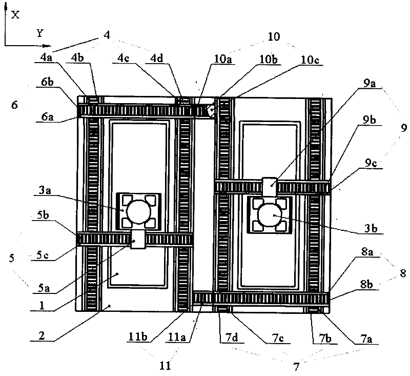
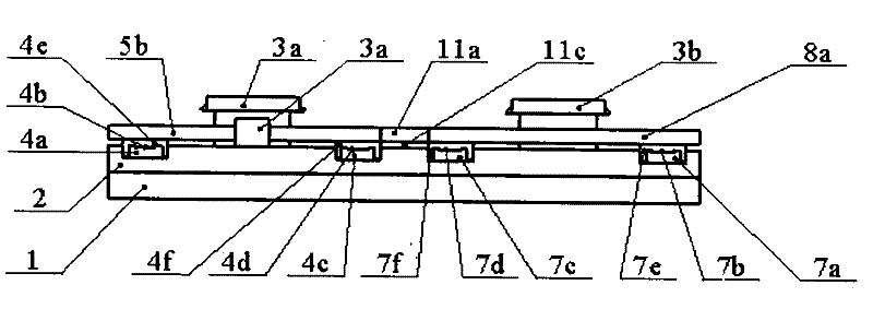
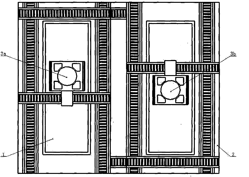
[0026] A dual workpiece stage exchange device based on single / dual drive step scanning. The system includes a base 1, a first wafer stage 3a set on the base 1 and running at a pre-alignment station, and an exposure tool The second silicon wafer stage 3b is arranged along the base 1 pre-aligned with the first static pressure air bearing guide rail 4a, the first linear motor stator 4b in the X direction, and the first linear motor moving in the X direction. Sub 4e, X-direction second static pressure air bearing guide 4c, X-direction second linear motor stator 4d, X-direction second linear motor mover 4f constituted X-direction first linear motion unit 4, X-direction first linear The moving unit 4 is provided with a Y-direction first linear motion unit 5 composed of a Y-direction first linear motor mover 5a, a Y-direction first linear motor stator 5b, and a Y-direction first static pressure air bearing guide 5c. The Y-direction second linear motion unit 6 is composed of the Y-dire...

Embodiment 2

[0034] It can be implemented by removing the X-direction second linear motor 4d, X-direction fourth linear motor 7d, Y-direction first transition linear motion unit 10 and Y-direction second linear motion unit 11 in the X-direction linear drive unit in Embodiment 1. Example 2, such as Figure 7 Shown. The process of exchanging the positions of the two workpiece tables in Embodiment 2 is exactly the same as in Embodiment 1. The difference is that the X-direction drive form of the two workpiece tables is dual-rail single-motor drive. Compared with Embodiment 1, the problem of inconsistency in X-direction dual-motor drive can be eliminated under the premise of ensuring the X-direction motion angular stiffness. At the same time, due to the omission of the transitional linear motion unit, the range of motion of the double-workpiece table can be increased, but the X-direction linear motor size is increased due to the X-direction driving force.

Embodiment 3

[0036] Remove the X-direction second linear motor 4d in the X-direction linear drive unit in Embodiment 1, the X-direction second static pressure air bearing guide 4c, the X-direction fourth linear motor 7d, the X-direction fourth static pressure air bearing guide, The Y-to-first transition linear motion unit 10 and the Y-to second linear motion unit 11 can obtain Embodiment 3, as Figure 8 Shown. The process of exchanging the positions of the two workpiece tables in Embodiment 3 is exactly the same as in Embodiment 1. Compared with Embodiment 1, Embodiment 2 reduces the X-direction linear drive unit in the X-direction second linear motor 4d, X-direction second static pressure air bearing guide 4c, X-direction fourth linear motor 7d, X-direction first The four static pressure air-floating guides, the Y-to-first transition linear motion unit 10 and the Y-to second linear motion unit 11 can also realize the station exchange of the two workpiece tables, but because the X-direction...


PUM


Abstract

The invention relates to a double work-piece stage exchanging device based on single/double drive stepping scanning, and a method thereof, and belongs to the technical field of semiconductor manufacturing equipment. The device comprises a base station, and work-piece stages, wherein the work-piece stages are respectively positioned on a pre-alignment working position and an exposure working position. 4 Y-direction linear movement units and 2 X-direction linear movement units are pre-arranged on a balancing mass block, and concurrently Y-direction transition linear movement units are arranged between the pre-alignment working position and the exposure working position. The movements of the work-piece stages between the pre-alignment area and the exposure area are completed through the docking of the linear motor stators of the Y-direction linear movement units and the Y-direction transition linear movement units so as to achieve the three-step work-piece stage exchanging. The first Y-direction linear motor mover is fixedly connected with the first work-piece stage, and the fourth Y-direction linear motor is fixedly connected with the second work-piece stage. According to the present invention, the three-step work-piece stage exchanging is adopted during the stage exchanging process so as to improve the stage exchanging efficiency; the device has characteristics of small movement inertia, short stabilization time, and avoidance of the clamp mechanism of the work-piece stage during the concrete device implementation process, and has advantages of compact structure, large structure stiffness, and the like.

Description

Technical field [0001] The invention belongs to semiconductor manufacturing equipment, and mainly relates to a dual-workpiece table exchange device and method based on single / dual drive step scanning. Background technique [0002] The lithography machine is one of the important ultra-precision system engineering equipment in semiconductor chip manufacturing. As the current mainstream lithography technology, the step-and-scan type puts forward higher requirements on the motion performance of the workpiece table. The main function of the workpiece stage is to carry the wafer under the conditions of high speed and high acceleration to realize nano-level positioning, complete the loading and unloading, pre-alignment, alignment and other processes in the photolithography process, and cooperate with the mask stage to complete the exposure action. Workpiece stage technology plays a vital role in improving the resolution, overlay accuracy and productivity of the lithography machine. [00...

Claims


Application Information

Patent Timeline
Patent Type & Authority Applications(China)
IPC IPC(8): G03F7/20H01L21/67H01L21/677
Inventor 谭久彬马伟崔继文金国良
Owner HARBIN INST OF TECH
Why Eureka
Try Eureka