
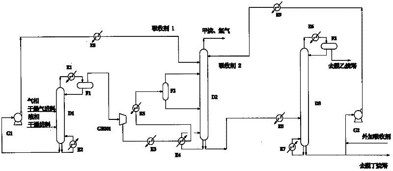
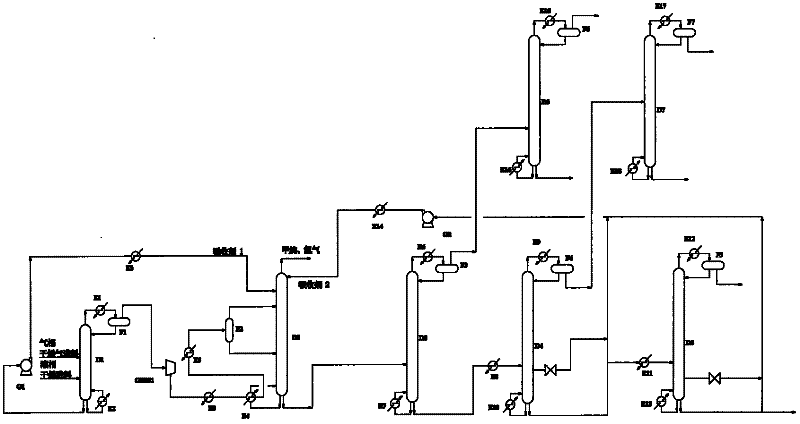
Process flow for separating low-carbon hydrocarbons and separating gas during production of olefins (M-OS/MTO) from methanol

A technology for methanol to olefins and gas separation, which is applied in the direction of absorption purification/separation, distillation purification/separation, ethylene production, etc. It can solve the problems of large towers and other equipment, long circulation routes, and large amount of absorbents, etc., to achieve reduction Investment and energy consumption, avoiding an increase in energy consumption, and enhancing the effect of absorption

Active Publication Date: 2012-06-20
SINOPEC SHANGHAI ENG +1
View PDF7 Cites 39 Cited by
  • Summary
  • Abstract
  • Description
  • Claims
  • Application Information

AI Technical Summary

Problems solved by technology

[0010] The currently industrialized Shenhua Baotou MTO plant uses propane-based absorbents to enter the top plate of the demethanizer to absorb components of C2 and above. The absorption efficiency is good, but the amount of absorbent is large and the absorption The agent comes from the follow-up separation system (propylene rectification tower still), and the circulation route is long, resulting in relatively large equipment such as towers, high investment and high energy consumption

Method used


Image

  • Process flow for separating low-carbon hydrocarbons and separating gas during production of olefins (M-OS/MTO) from methanol
  • Process flow for separating low-carbon hydrocarbons and separating gas during production of olefins (M-OS/MTO) from methanol
  • Process flow for separating low-carbon hydrocarbons and separating gas during production of olefins (M-OS/MTO) from methanol

Examples


Embodiment Construction

[0028] The following is an embodiment of the present invention, based on the composition of the methanol-to-olefins reaction gas with an annual output of 600,000 tons of olefins in a plant as the feed, wherein the ratio of ethylene to propylene is about 1:1, and the attached image 3 The process flow is separated. The protection scope of the present invention is not limited to the following specific embodiments.

[0029] In this embodiment, the reaction gas produced by methanol through catalytic reaction is gradually increased to 2.0 MPaG, and after cooling, it is divided into two phases of gas and liquid, which are respectively sent into the drying system for drying. The dried reaction gas enters the absorbent separation tower D1, the top of the absorbent separation tower is mainly methane, hydrogen, carbon two and some carbon three, and the main components of the tower bottom are carbon three, carbon four and the recombination of carbon four or more points, is an unclear pa...


PUM


Abstract

The invention provides a non-cryogenic oil absorption separation method for a mixture of low-carbon hydrocarbons, which is used for separating the mixture of the hydrocarbons from gas during production of olefins from methanol. Methane / hydrogen can be separated from heavy components, namely C2 and above by absorbing fractions of the C2 and above by adopting two or more strands of absorbing agents. According to the method disclosed by the invention, an absorbing agent separating tower is increased before a demethanization tower, one strand of material flow, which is separated from the tower is taken as a main absorbing agent of the demethanization tower for absorbing the C2 and C3, the strand of the absorbing agent is the mixture of the fractions, which is from the former system and needs to be separated, and circulation is not required. The second strand of the absorbing agent of the demethanization tower is from a system including a depropanization tower and a debutanization tower, and the absorption effect is further enhanced. Compared with the prior art, the method can greatly reduce the using quantity of the circulating absorbing agents; moreover, the multiple strands of the absorbing agents are adopted, equipment investment and energy consumption are significantly reduced, the recovery rate of ethylene and propylene is further improved; and furthermore, the flow is simple, the operation cost is low, and the operation is safe and reliable.

Description

technical field [0001] This low-carbon hydrocarbon separation and methanol-to-olefins (M-OS / MTO) gas separation process is suitable for oxidation to olefins, hydrocarbon cracking, hydrocarbon catalytic reaction to produce olefins, and is also suitable for traditional petrochemical ethylene fields. Background technique [0002] Most of the intermediate and final products in the petrochemical industry are based on olefins and aromatics. The ethylene unit is the main production unit for the production of olefins (ethylene, propylene, butadiene) and aromatics. In the past, olefins were mainly produced by thermal cracking of naphtha through a tube furnace. In recent years, due to the shortage of petroleum resources, the methanol-to-olefins (MTO / MTP) technology has been gradually developed and entered the stage of industrialization. Methanol-to-olefins technology consists of reaction technology and separation technology. Reaction technology is centered on the development and des...

Claims


Application Information

Patent Timeline
Patent Type & Authority Applications(China)
IPC IPC(8): C07C7/11C07C7/04C07C11/02C07C11/04C07C11/06
CPCY02P30/40
Inventor 王松汉李莉裴雪梅
Owner SINOPEC SHANGHAI ENG
Learn More