Infrared light simulated shooting training system
A training system, infrared light technology, applied in the field of integrated systems, can solve the problems of high cost of photosensitive equipment, easy to be affected by external stray light, light attenuation, etc., to achieve the effect of reducing bullet consumption, clear trajectory tracing, and fast response speed
- Summary
- Abstract
- Description
- Claims
- Application Information
AI Technical Summary
Problems solved by technology
Method used
Image

Examples
Embodiment 1
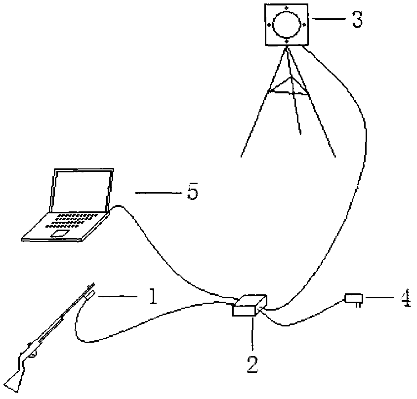
[0021] Embodiment 1: The schematic diagram of the functional structure of the infrared light simulation shooting training system is as follows figure 1 As shown, the analog shooting controller is connected to the infrared receiver through the serial port, and connected to the microcomputer through the USB interface. The power cable plug of the infrared target is inserted into the power output jack, and the infrared receiver is fixed on the gun barrel. Below the front end, then, power the analog shooter controller via the power input jack. Aiming at the infrared light target, the main interface of the simulated shooting can track the trajectory of the aiming point on the display of the microcomputer, and the impact point can be determined on the simulated target paper by the sound of firing the firing pin. The target position can be predicted by each target position and aiming point trajectory.
Embodiment 2
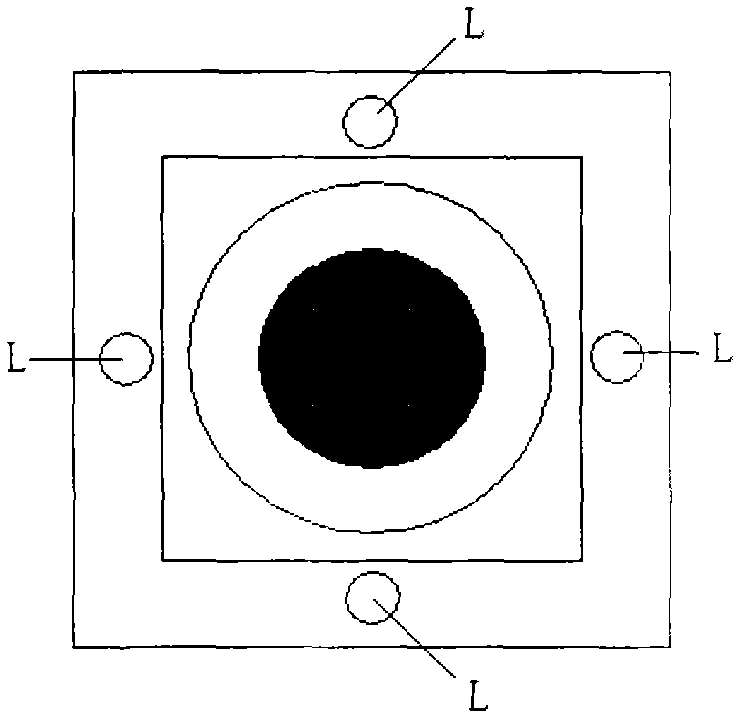
[0022] Embodiment 2: The simulated shooting system can realize the tracking of the aiming point trajectory, but some simulated shooting systems install light-emitting tubes on the side of the gun and light-sensitive devices on the target side. This method has too high technical requirements for the target side. It's more about image recognition. In this embodiment, four infrared light-emitting tubes are placed at the four corners of the target or the midpoints of the four sides, such as figure 2 As shown, the position sensor is fixed on the lower part of the gun barrel, and the infrared rays emitted from the four light-emitting tubes pass through the lens of the position sensor and are projected onto the photosensitive surface of the position sensor, which can be equivalently considered to form a composite light spot, so that Calculate the specific positional parameters.
Embodiment 3
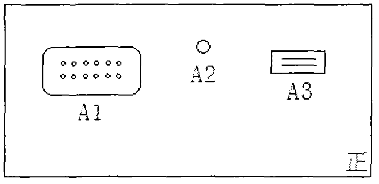
[0023] Example 3: image 3 with Figure 4 A schematic diagram of the functional structure of the simulated shooting controller is illustrated
PUM
 Abstract
Description
Claims
Application Information
 - R&D Engineer
- R&D Manager
- IP Professional
- Industry Leading Data Capabilities
- Powerful AI technology
- Patent DNA Extraction
Browse by: Latest US Patents, China's latest patents, Technical Efficacy Thesaurus, Application Domain, Technology Topic.
© 2024 PatSnap. All rights reserved.Legal|Privacy policy|Modern Slavery Act Transparency Statement|Sitemap