Method for generating arbitrary waveforms on basis of optical injection locking

An arbitrary waveform and optical injection technology, which is applied in the field of microwave signal sources, can solve the problem of low maximum frequency and achieve the effects of stable amplitude, narrow optical signal line width and high fitting degree

Inactive Publication Date: 2012-06-27
TIANJIN UNIV
View PDF3 Cites 4 Cited by
  • Summary
  • Abstract
  • Description
  • Claims
  • Application Information

AI Technical Summary

Problems solved by technology

[0010] The purpose of the present invention is to solve the problem that the highest frequency of the signal generated by the existing arbitrary waveform generator is relatively low and can only reach tens of MHz, and proposes an arbitrary waveform generator based on optical injection locking. Through the method of optical injection locking, the The broadband comb spectrum signal is injected into each DFB laser, and the phase, frequency, and amplitude of the difference frequency signal generated by the optical signal generated by the mode-locked DFB laser are stable, and they can be adjusted separately by a simple method, and then each Synthesis of sub-harmonics, so that the desired waveform can be obtained

Method used


Image

  • Method for generating arbitrary waveforms on basis of optical injection locking
  • Method for generating arbitrary waveforms on basis of optical injection locking
  • Method for generating arbitrary waveforms on basis of optical injection locking

Examples


Embodiment 1

[0031] Embodiment 1, (the number of DFB lasers is 8, n=3)

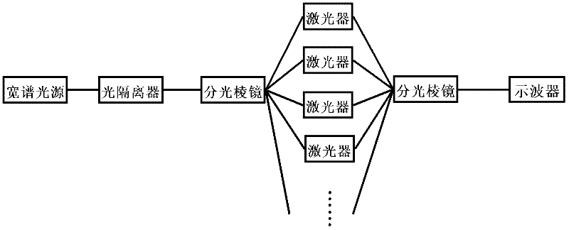
[0032] Such as Figure 4 Shown in (a) is the composition block diagram of a kind of arbitrary waveform generator of this method, which includes direct modulation laser, microwave source, optical isolator, 22 depolarizing beam splitters (including 15 before injection and output coupling 7), 8 distributed feedback semiconductor lasers (DFB-LD), 8 adjustable optical power attenuators.

[0033]The directly modulated laser is modulated by a microwave source to form a signal with a broadband comb spectrum. In this embodiment, the bandwidth that can be used for injection locking is set between 400 GHz and 500 GHz. The signal passes through an optical isolator and then passes through 15 depolarization stages. The beam-splitting prism is injected into 8 DFB lasers, and there are 4 depolarized beam-splitting prisms between each laser and the direct modulation laser. The function of the optical isolator is to prevent the light ...

Embodiment 2

[0047] Embodiment 2, (the number of DFB lasers is 4, n=2)

[0048] Such as Figure 4 Shown in (b) is the block diagram of another arbitrary waveform generator of this method, which includes a direct modulation laser, a microwave source, an optical isolator, 10 depolarizing beamsplitters (including 7 before injection and output coupling 3), 4 distributed feedback semiconductor lasers (DFB-LD), 4 adjustable optical power attenuators.


PUM


Abstract

The invention provides a new method for generating arbitrary waveforms on the basis of optical injection locking, which adopts the optical injection locking technology to keep multiple channels of optical signals stable relatively so as to generate arbitrary waveforms according to different harmonic components which are composed of difference frequencies of the optical signals. A wide-band light source is injected into multiple distributed feedback semiconductor lasers through an optical isolator and a series of beam splitter prisms sequentially, and mode locking is realized after working temperature and current of each laser are regulated. Phase and amplitude of output optical signals of the lasers are changed respectively by regulating the spatial positions of the lasers and dimmable power attenuators in output optical paths. Different channels of difference-frequency signals with adjusted phase and amplitude are coupled through the optical paths, so that arbitrary waveforms are generated finally. The method can be used for generation of arbitrary waveforms in the frequency ranging from several Ghz to dozens of Ghz, and can be applied to multiple fields of manufacturing of ultrahigh signal generation equipment, testing of communicating systems, radar communication and the like widely.

Description

Technical field: [0001] The invention belongs to the technical field of microwave signal sources, and relates to a method for generating arbitrary waveforms based on optical injection locking. Background technique: [0002] Waveform generator is a signal generating device and signal source widely used in circuit design, debugging and measurement. The general signal source can only generate several fixed-shaped waveforms, but the Arbitrary Waveform Generator can create and generate any conceivable waveform. Its leading, easy-to-use and flexibility greatly facilitate people's design and debugging. AWG can generate various waveforms for analog field signals and various signal synthesis. [0003] With the continuous deepening of scientific and technological research and the expansion of fields, the signals used for simulation are required to be more complex and diverse. For example, each step in the development of communication requires different test signals. Improvements i...

Claims


Application Information

Patent Timeline
IPC IPC(8): G02F1/35G02B27/28
Inventor 于晋龙孙斌
Owner TIANJIN UNIV
Why Eureka
Try Eureka