Nuclear power generator test device

A test device and generator technology, applied in electrical program control, comprehensive factory control, comprehensive factory control, etc., can solve the problems of low adjustment accuracy of variable frequency units, poor time synchronization, and low accuracy of manual measurement and sampling values. Easy to query, ensure simultaneity, and save labor

Active Publication Date: 2012-06-27
哈尔滨五联电气设备有限责任公司
View PDF8 Cites 2 Cited by
  • Summary
  • Abstract
  • Description
  • Claims
  • Application Information

AI Technical Summary

Problems solved by technology

[0003] In order to solve the existing 10-million-megawatt-level generator test process, the adjustment of the frequency conversion unit is realized through the adjustment of the sliding rheostat, and for the detection and collection of thermal work during the test process, it is necessary for the staff to manually read the thermal energy. Due to the problems of low adjustment accuracy of variable frequency units, low accuracy of manual measurement of sampling values, and poor time synchronization in the workload values, the proposed nuclear power generator test device

Method used


Image

  • Nuclear power generator test device
  • Nuclear power generator test device
  • Nuclear power generator test device

Examples


specific Embodiment approach 1

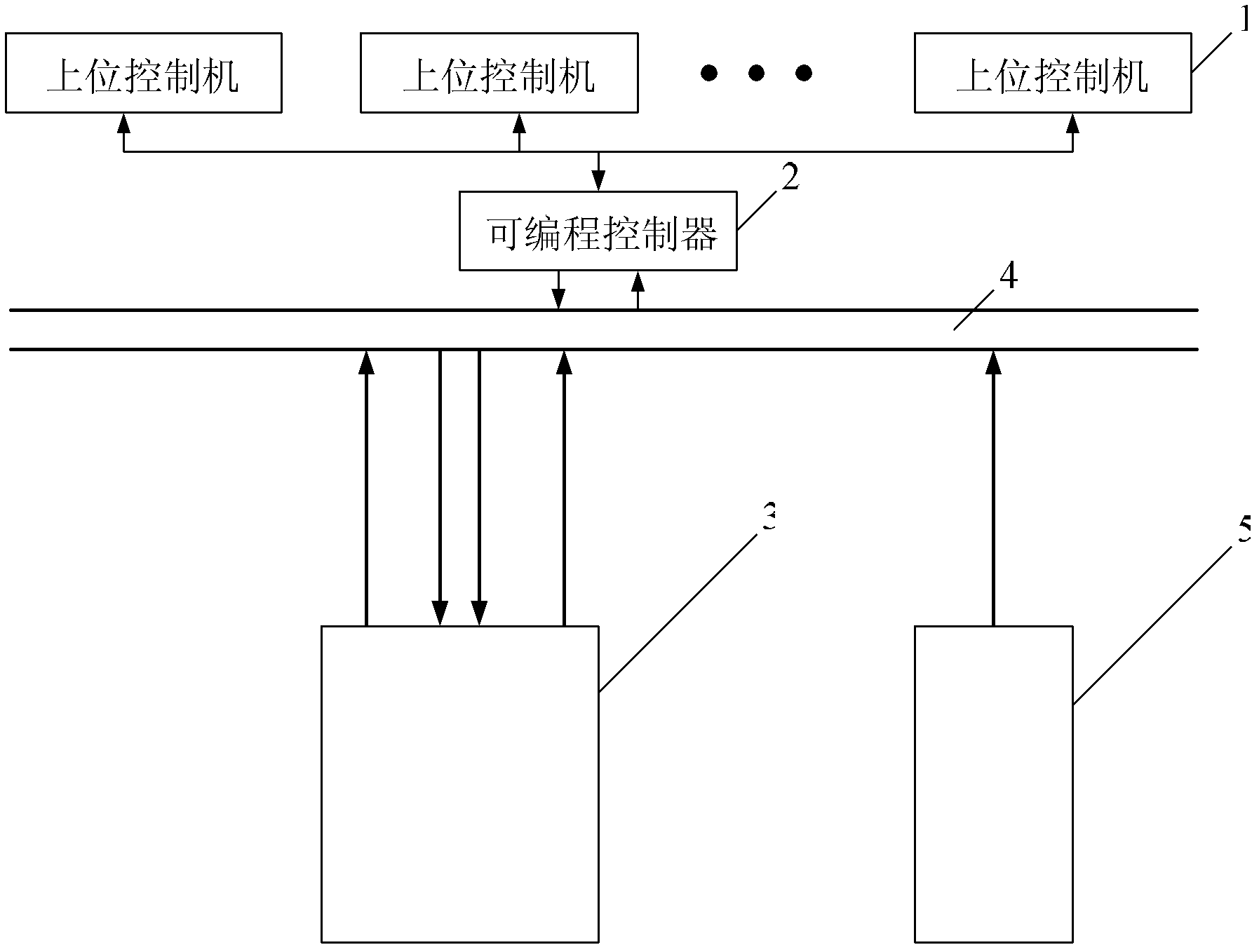
[0016] Specific implementation mode one: combine figure 1 Describe this embodiment, the nuclear power generator test device described in this embodiment, it is made up of M upper control machine 1, programmable controller 2, electrical monitoring system 3, field bus 4 and non-electrical monitoring system 5; M is positive Integer; the sampling data and control signal input and output terminals of each host controller 1 are connected to the sampling data and control signal output and input terminals of the programmable controller 2 through industrial Ethernet; the sampling data of the programmable controller 2 The data input terminal is connected with the first sampling data output terminal of the electrical monitoring system 3, the second sampling data output terminal of the electrical monitoring system 3 and the sampling data output terminal of the non-electrical monitoring system 5 through the field bus 4; the programmable control The control signal output end of the device 2...

specific Embodiment approach 2

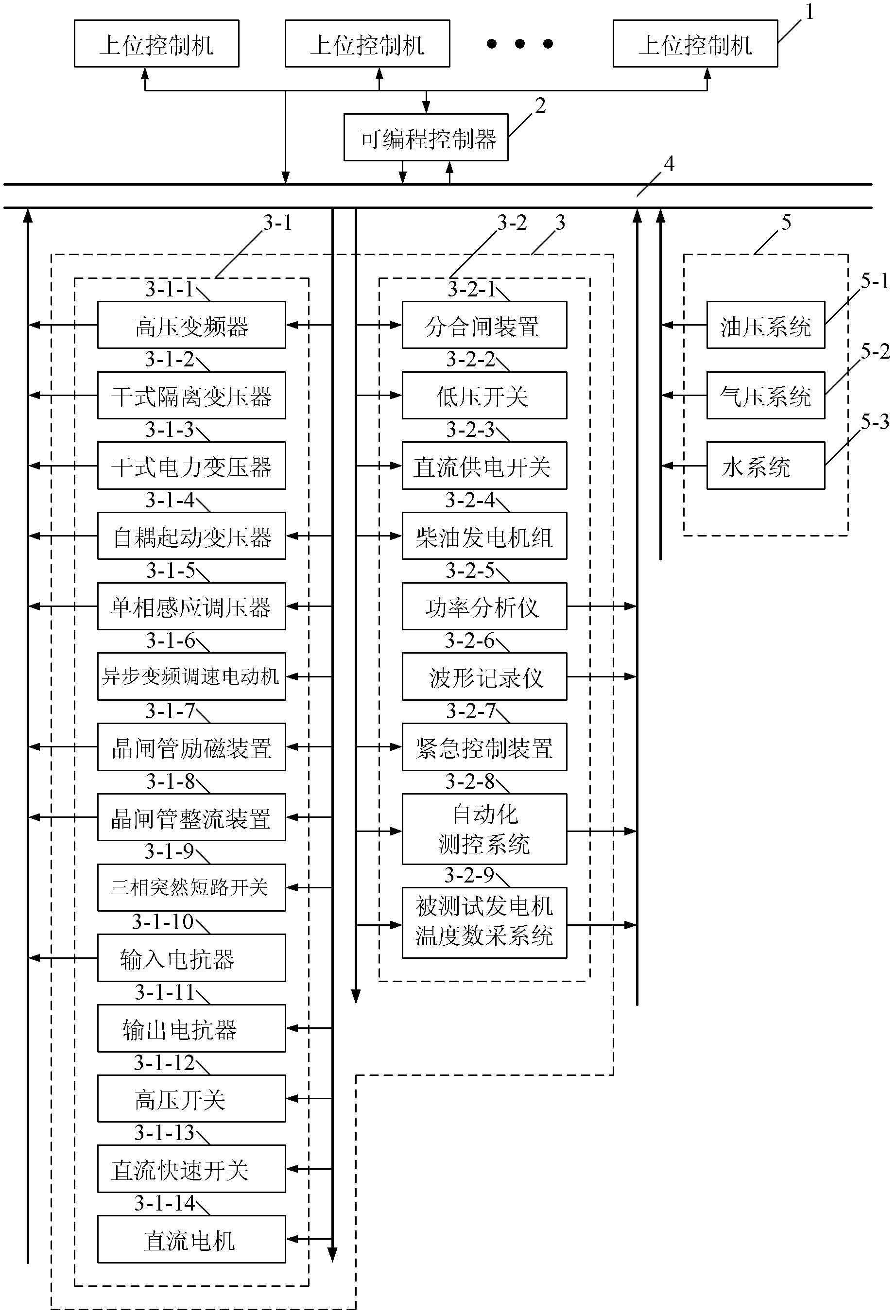
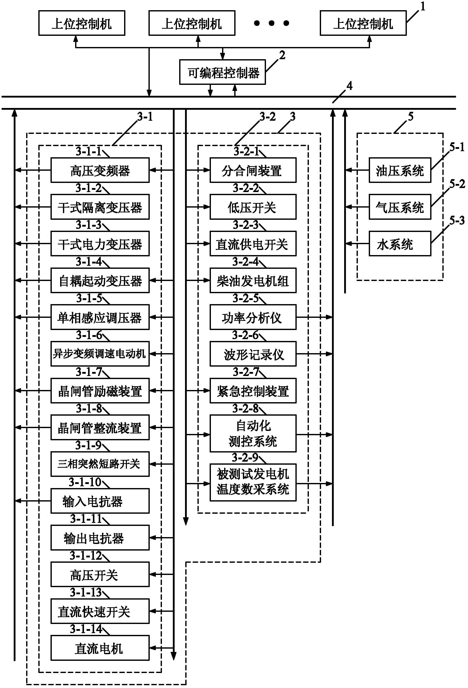
[0017] Specific implementation mode two: combination figure 2 Describe this embodiment, the first difference between this embodiment and the specific embodiment is that the electrical monitoring system 3 is composed of a high-voltage monitoring system 3-1 and a low-voltage monitoring system 3-2; the sampling data output of the high-voltage monitoring system 3-1 end is the first sampling data output end of the electrical monitoring system 3; the sampling data output end of the low-voltage monitoring system 3-2 is the second sampling data output end of the electrical monitoring system 3. Other compositions and connection methods are the same as those in Embodiment 1. The electrical monitoring system 3 mainly includes an electrical system, an electric drive system and an excitation system. The tester performs functions such as centralized control of the test device through the upper control machine 1, state monitoring, recording and analysis of relevant test data, and will Save...

specific Embodiment approach 3

[0018] Specific implementation mode three: combination figure 2 Describe this embodiment. The difference between this embodiment and the second specific embodiment is that the high-voltage monitoring system 3-1 consists of a high-voltage frequency converter 3-1-1, a dry-type isolation transformer 3-1-2, and a dry-type power transformer 3- 1-3. Auto-coupling starter transformer 3-1-4, single-phase induction voltage regulator 3-1-5, asynchronous frequency conversion speed regulation motor 3-1-6, thyristor excitation device 3-1-7, thyristor rectifier device 3 -1-8, three-phase sudden short circuit switch 3-1-9, input reactor 3-1-10, output reactor 3-1-11, high voltage switch 3-1-12, DC fast switch 3-1-13 and DC motor 3-1-14; the sampling data output terminal of the high-voltage frequency converter 3-1-1 is connected to the high-voltage side data bus, and the control signal output terminal of the high-voltage frequency converter 3-1-1 is connected to the high-voltage side signal ...


PUM


Abstract

The invention provides a nuclear power generator test device and relates to a nuclear power generator test device, which is provided by aiming at solving the problems that in the existing ten million megawatt level generator test process, the regulation of a frequency conversion unit is realized through the regulation of a slide rheostat, the manual reading of the thermotechnical quantity value by work personnel is need for the detection and the collection aiming at the thermotechnical quantity in the test process, the regulation precision of the frequency conversion unit is low, the precision of the artificial measurement sampling value is low, and the time synchronism is poor. The sampling data and control signal input and output end of a host machine is connected with the sampling data and control signal output and input end of a programmable controller, the sampling data input end of the programmable controller is simultaneously connected with a first sampling data output end and a second sampling data output end of an electric monitoring system and a sampling data output end of a non-electric monitoring system, and the control signal output end of the programmable controller is simultaneously connected with the first control signal input end and the second control signal input end of the electric monitoring system and the control signal input end of the non-electric monitoring system. The nuclear power generator test device has the advantages that the regulation precision is high, the thermotechnical quantity is detected and collected in real time, and the data precision is high.

Description

technical field [0001] The invention relates to a nuclear power generator test device. Background technique [0002] With the improvement of nuclear power technology, the installed capacity of nuclear power plants is getting higher and higher, and 10 million megawatt nuclear power generators are also being used more and more. However, during the test process of the existing 10 million megawatt generators, The voltage regulation, excitation regulation, and frequency regulation of the frequency conversion unit are all realized by adjusting the excitation current of the DC machine and the synchronous motor through the sliding rheostat, and it is difficult to guarantee the accuracy; For the detection and collection of thermal quantities of the system, it is necessary to assign corresponding staff at each collection point to manually read the thermal quantities, such as temperature, pressure, flow, liquid level, etc., and all personnel will uniformly record the values ​​after the...

Claims


Application Information

Patent Timeline
Patent Type & Authority Applications(China)
IPC IPC(8): G05B19/418
CPCY02P90/02
Inventor 马琨鹏陈涛孙剑峰马嗣钰刘洋王宁
Owner 哈尔滨五联电气设备有限责任公司
Why Eureka
Try Eureka