Ring dielectric barrier discharge ionization device

A dielectric barrier discharge and discharge electrode technology, applied in electrical components, plasma, ion source/gun, etc., can solve the problems of metal electrode and discharge area pollution, partial discharge and discharge instability, etc., to avoid partial discharge and discharge Effects of instability, low power consumption, and strong oxidation resistance

Inactive Publication Date: 2012-06-27
KUSN HEXIN MASS PECTRUM TECH
View PDF6 Cites 28 Cited by
  • Summary
  • Abstract
  • Description
  • Claims
  • Application Information

AI Technical Summary

Problems solved by technology

The technical problem to be solved by the present invention is: the problem of partial discharge and discharge instability existing in the prior art, and the problem of pollution caused by the contact of the metal electrode with the discharge area

Method used


Image

  • Ring dielectric barrier discharge ionization device
  • Ring dielectric barrier discharge ionization device
  • Ring dielectric barrier discharge ionization device

Examples


Embodiment 1

[0027] Example 1, see figure 2 Shown:

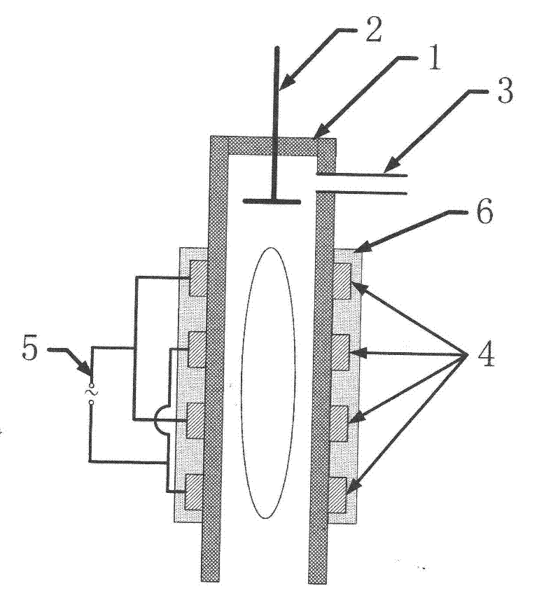
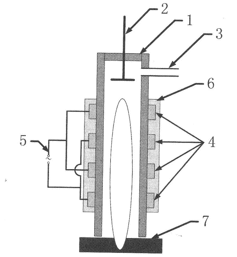
[0028] An annular dielectric barrier discharge ionization device of the present invention comprises an insulating medium cavity 1, a discharge electrode 4, a repelling electrode 2, an insulating medium 6 and a power supply 5, one end of the insulating medium cavity 1 is open, the other end is closed and close to the closed The gas inlet 3 is provided on the side wall of the end; the discharge electrode 4 is a group of ring electrodes, which are tightly surrounded outside the middle part of the insulating medium cavity 1 and covered with an annular hollow insulating medium 6; the repelling electrode 2 is a round Shaped metal plate is placed inside the closed end of the insulating medium cavity 1 and above the discharge electrode 4; the power supply 5 supplies power to the discharge electrode 4; the opening end of the insulating medium cavity 1 is connected to the fabric 7.

[0029] The insulating medium chamber 1 is made of quartz, with...

Embodiment 2

[0031] Example 2, see image 3 Shown:

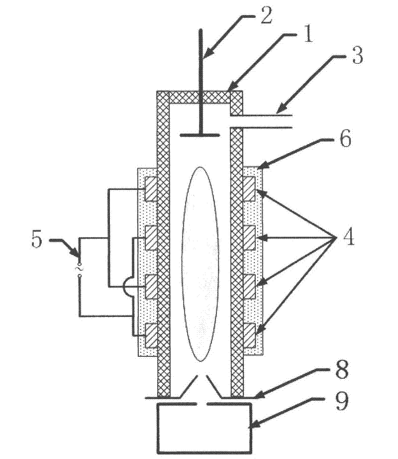
[0032] An annular dielectric barrier discharge ionization device of the present invention comprises an insulating medium cavity 1, a discharge electrode 4, a repelling electrode 2, an insulating medium 6 and a power supply 5, one end of the insulating medium cavity 1 is open, the other end is closed and close to the closed A gas inlet 3 is provided on the side wall of the end; the discharge electrode 4 is a group of annular electrodes, which are closely surrounded outside the middle part of the insulating medium chamber 1 and covered with an annular hollow insulating medium 6; the repelling electrode 2 is a round Shaped metal plate, placed inside the closed end of the insulating medium cavity 1, and above the discharge electrode 4; the power supply 5 supplies power to the discharge electrode 4, and the opening end of the insulating medium cavity 1 is connected to the tapered lens in turn 8 with a mass analyzer 9 .

[0033] The insulati...

Embodiment 3

[0035] Example 3, see figure 2 Shown:

[0036] The structure of this embodiment is basically the same as that of Embodiment 1. The material of the insulating medium cavity 1 is ceramic, the inner diameter is 9 mm, and the length is 200 mm. The number of the discharge electrodes is 100, the electrode spacing is 0.8 mm, and the electrode width is 0.8 mm. The gas flowing into the cavity is air, the flow rate is 5mL / min, and the pressure in the cavity is 10Pa. The repeller electrode 2 is a circular metal plate, located 1mm above the nearest discharge electrode 4, and a positive voltage of 20V is applied. The power supply 5 is a high-voltage AC power supply, which alternately applies voltages at both ends of the power supply to adjacent discharge electrodes. The power frequency is 9kHz and the working power is 10W.


PUM


Abstract

The invention relates to an ionization device, in particular to a ring dielectric barrier discharge ionization device, which comprises an insulating medium cavity, discharge electrodes, a repeller electrode, an insulating medium and a power supply, wherein one end of the insulating medium cavity is open, and the other end of the insulating medium cavity is closed; a gas inlet is formed in a sidewall close to the closed end of the insulating medium cavity; the discharge electrodes are ring electrodes which form a group, closely surround the periphery of the middle part of the insulating medium cavity, and are clad by the insulating medium; the repeller electrode is a circular metal plate, and is arranged in the closed end of the insulating medium cavity and positioned above the discharge electrodes; and the power supply supplies power to the discharge electrodes. The ring dielectric barrier discharge ionization device has the characteristics of discharge stability, no electrode pollution, oxidation resistance, low power consumption, long service life, wide working air pressure range and the like, and can be widely applied in the fields of mass spectrometric ionization sources, plasma treatment, material preparation and the like.

Description

technical field [0001] The invention relates to an ionization device, in particular to an annular dielectric barrier discharge ionization device. Background technique [0002] Plasma technology is widely used in ozone generation, environmental protection, surface treatment of textile materials and other fields. The ways to achieve ionization mainly include glow discharge, dielectric barrier discharge, spark discharge and so on. Among them, the dielectric barrier discharge has the characteristics of stable discharge, high efficiency, and the ability to avoid electrode pollution, so it has become one of the important ionization methods and is widely used in surface treatment, material preparation, material modification, material cleaning and other fields. Chinese patent CN200810227016.0 introduces that this device can also be used in the field of mass spectrometry. As an ionization source in mass spectrometry, it has the advantages of low power consumption and high ionization...

Claims


Application Information

Patent Timeline
Patent Type & Authority Applications(China)
IPC IPC(8): H01J49/12H05H1/32
Inventor 吴庆浩程平黄正旭高伟董俊国周振傅忠
Owner KUSN HEXIN MASS PECTRUM TECH
Why Eureka
Try Eureka