
Technical device for recycling tail gas and residual heat during production of active carbon with phosphoric acid method

A technology of activated carbon production and waste heat recovery, applied in the field of activated carbon production, can solve the problems of energy waste, large heat energy consumption, high concentration cost, etc., and achieve the effects of reducing energy consumption, reducing pollution, and purifying the environment

Active Publication Date: 2012-07-04
福建省芝星炭业股份有限公司
View PDF8 Cites 5 Cited by
  • Summary
  • Abstract
  • Description
  • Claims
  • Application Information

AI Technical Summary

Problems solved by technology

[0004] In the above two processes, the former wastes a lot of waste heat of phosphoric acid tail gas, and the high temperature phosphoric acid tail gas has higher requirements for its subsequent treatment equipment, while the latter consumes a lot of heat energy, which causes a huge waste of energy
[0005] The phosphoric acid activated carbon production line needs to concentrate industrial phosphoric acid at 25 degrees Baumé every day. The existing process is to concentrate phosphoric acid with a graphite heat exchanger, and the concentration cost is high.

Method used


Image

  • Technical device for recycling tail gas and residual heat during production of active carbon with phosphoric acid method
  • Technical device for recycling tail gas and residual heat during production of active carbon with phosphoric acid method
  • Technical device for recycling tail gas and residual heat during production of active carbon with phosphoric acid method

Examples


Embodiment Construction

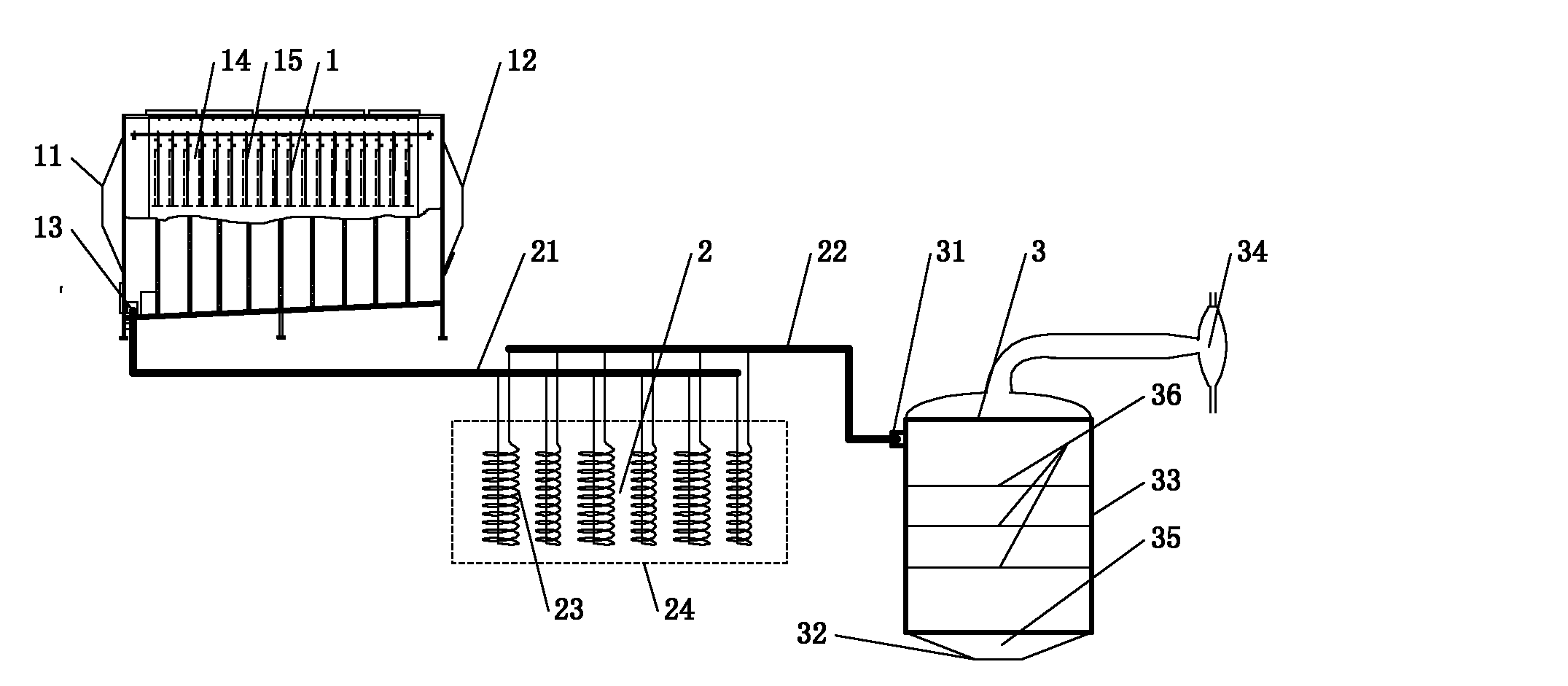
[0017] Such as figure 1 As shown, the present invention phosphoric acid activated carbon production tail gas and waste heat recovery and reuse technology device includes phosphoric acid tail gas collection device 1, phosphoric acid tail gas waste heat utilization device 2 and concentrated residual phosphoric acid energy saving device 3; the phosphoric acid tail gas input terminal 11 of the phosphoric acid tail gas collection device is connected to To the kiln phosphoric acid tail gas flue, the phosphoric acid tail gas output port 12 is connected to the emptying port, the dilute phosphoric acid collection tank 13 is connected to the dilute phosphoric acid input port 21 of the phosphoric acid tail gas waste heat utilization device 2; the output 22 of the phosphoric acid tail gas waste heat utilization device 2 is connected to The input end 31 of the concentrated residual phosphoric acid energy saving device 3; the output end 32 of the concentrated residual phosphoric acid energy ...


PUM


Abstract

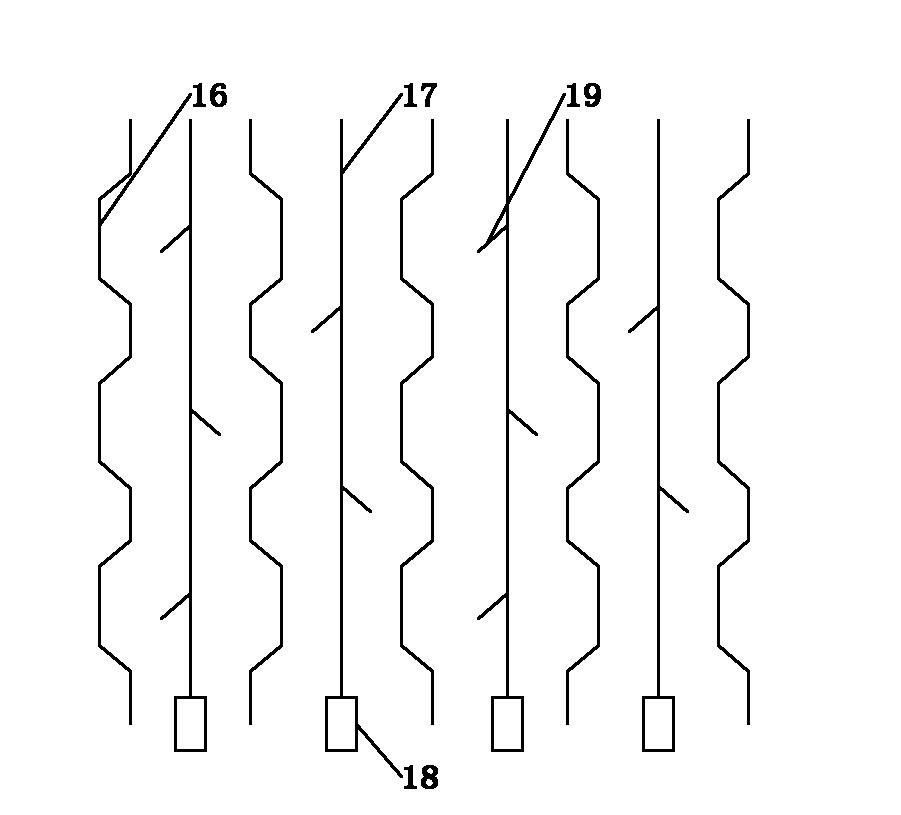
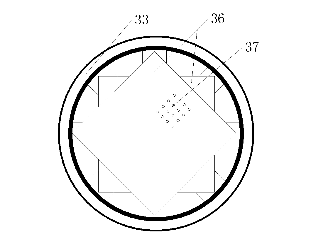
The invention provides a technical device for recycling tail gas and residual heat during production of active carbon with a phosphoric acid method. The technical device comprises a phosphoric acid tail gas collecting device, a phosphoric acid tail gas residual heat utilizing device and a concentrated residual phosphoric acid energy-saving device, wherein the phosphoric acid tail gas input end of the phosphoric acid tail gas collecting device is connected to a kiln phosphoric acid tail gas flue; the phosphoric acid tail gas output end of the phosphoric acid tail gas collecting device is connected to an emptying port; a diluted phosphoric acid collecting groove is connected to the diluted phosphoric acid input end of the phosphoric acid tail gas residual heat utilizing device; the output of the phosphoric acid tail gas residual heat utilizing device is connected to the input end of the concentrated residual phosphoric acid energy-saving device; and the output end of the concentrated residual phosphoric acid energy-saving device is connected to a concentrated phosphoric acid recovering pool. Phosphoric acid tail gas is treated through an electric demisting device with a honeycomb electrode structure, phosphoric acid tail gas residual heat is utilized by arranging more than two groups of heat exchange tubes in the flue, phosphoric acid is concentrated under a vacuum condition through a sieve through hole structure, and phosphoric acid recovery and residual heat reutilization of tail gas during production of active carbon with the phosphoric acid method are realized, so that energy consumption is lowered, and pollution is lowered.

Description

technical field [0001] The invention relates to the technical field of activated carbon production, in particular to a technical device for recovering and reusing exhaust gas from phosphoric acid activated carbon production and waste heat. technical background [0002] In the existing treatment method of phosphoric acid tail gas in the kiln during the production process of activated carbon by phosphoric acid method, the water washing method is used to treat the absorption liquid, which will face the problem of secondary pollution, and the effect of using auxiliary block demisting and wire mesh packing demisting is not as good. It is not very ideal, but the use of electrostatic demisting device to treat the phosphoric acid tail gas of phosphoric acid can achieve stable purification quality and avoid the problem of secondary pollution. [0003] At present, the phosphoric acid tail gas treatment process of activated carbon production is usually that the phosphoric acid tail gas...

Claims


Application Information

Patent Timeline
Patent Type & Authority Applications(China)
IPC IPC(8): B01D53/32C01B31/08C01B25/234F27D17/00C01B32/312
CPCY02P20/10
Inventor 魏安国
Owner 福建省芝星炭业股份有限公司
Learn More